Wall mounting racks using vibration pads, Floor mounting racks using vibration pads, N o t e – ETC Sensor3 CE (ESR3) Rack User Manual
Page 16
8
Sensor3 CE Rack (ESR3) Installation Manual
Wall Mounting Racks Using Vibration Pads
Vibration damping fittings are available as an option
for wall mounted racks. The wall must be strong
enough to hold the racks. Please see
Sensor3 CE Rack Specifications, page 34
for rack
and module weights.
Step 1:
Mark the hole locations on the wall from
Figure 2: ESR3-12 and ESR3-24 wall
Step 2:
Align the center of the fitting over the hole locations from the diagram. Mark the
position for two fitting bolts for each vibration pad (the middle holes are
recommended).
Step 3:
Drill the holes and secure the fittings to the wall. You must supply your own M10
mounting hardware.
Step 4:
Remove the included bolt and washer from each vibration fitting.
Step 5:
Position the rack on the wall so the centers of the vibration fittings align with the
wall mounting slots.
Step 6:
Secure the rack to its vibration pad with the included bolts and washer.
Floor Mounting Racks Using Vibration Pads
ESR3-36 and ESR3-48 racks can be floor mounted on
optional vibration damping fittings (ETC
Part# HW6109).
Step 1:
Determine where your rack will be installed
Figure 1: Sensor3 rack clearances on
.
Step 2:
Use the appropriate diagram from
Figure 3: Hole diagrams for mounting racks
N o t e :
Be sure this mounting method complies
with your countries building and electrical
codes.
N o t e :
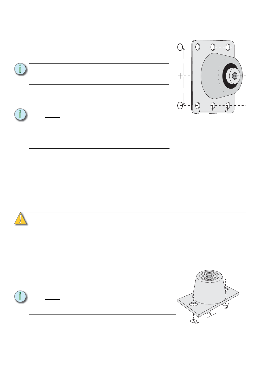
ETC’s wall mount vibration pads (ETC
Part# HW6111) attach to racks with the
provided bolts that are slightly larger than
the top of the keyhole slots. The bolt works
fine installed in the lower portion of the slot,
but the rack will mount slightly higher
(approx. 10mm) than the diagram indicates.
C A U T I O N :
Unless the all mounting and connections are done in a flexible manner, the
effectiveness of the vibration pads will be reduced or completely negated. This
includes the use of at least 30cm of flexible conduit or flexible cable for all of the
electrical connections to the rack(s).
N o t e :
Be sure this mounting method complies with
local building and electrical codes.
Level racks before marking the hole positions.
Figure 4: Positioning a vibration pad
on a wall
Align the center of the fitting over the diagram
hole location and mark the position of the fitting
bolts
50cm
50cm
25cm
25cm
ETC Part# HW6111
Figure 5: Floor vibration pad
Center the fitting over the mount hole location
from the diagram and mark the positions for the
fitting hardware
ETC Part#
HW6109
38mm
38mm