Ethernet network termination - rj45 connector, Panic circuit connections (optional), Panic circuit backplane connection – ETC Sensor3 CE (ESR3) Rack User Manual
Page 31
4
Control and Data Connections
23
Ethernet Network Termination - RJ45 Connector
Step 1:
Follow the directions provided in the Ethernet Termination Kit to terminate the
incoming CAT5 cable in the RJ45 UTP connector in the surface mounting box.
The kit is included with the dimmer rack door. Use the instructions provided with the kit for
proper Category 5 cable termination.
Step 2:
The surface mount box should be installed with the double-sided tape inside the
rack.
•
ESR3-36, ESR3-48: To the underside of the CEM3 backplane bracket.
•
ESR3-12, ESR3-24: To the bottom of the rack behind the backplane.
Step 3:
Use the provided male-to-male Ethernet patch cable to connect the surface
mounting box female RJ45 connector to the female RJ45 connector on the
CEM3 backplane.
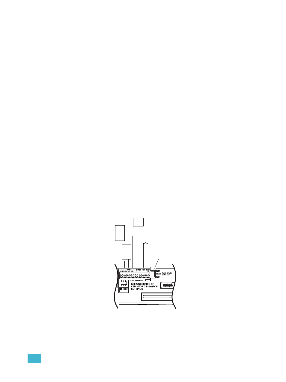
Panic Circuit Connections (Optional)
Sensor3 racks can connect to an external Panic circuit if desired. Panic can be triggered by
a normally open or normally closed contact. The racks can also provide a feed to a lamp or
LED to indicate whether panic is active.
Panic Circuit backplane connection
Step 1:
Pull two 1.5mm
2
wires from your Panic contact location to the CEM3 backplane
through the data cable conduit or trunking. See
for data conduit installation details.
Step 2:
Connect the wires to the connector on the CEM3 backplane. Connect the Panic
contact input between “PANIC RTN” and “PANIC IN”.
Step 3:
Optionally, connect an external panic indication lamp between “PANIC OUT” and
“COM”. When panic is active, there will be a supply of +24VDC between “PANIC
OUT” and “COM”, with a maximum current draw of 25mA.
Step 4:
Set the switch on the backplane to indicate the contact type: Normally Open (NO)
or Normally Closed (NC).
Maintained
Closure
To trigger Panic,
use a
To external
indicators
(such as a
lamp or relay)
+24Vdc
(max 25mA
each)
To external
indicators
(such as a
lamp or relay)
+24Vdc
(max 25mA
each)
For Panic SEND/RTN:
NO - Normally Open closure
Disabled - Panic Disabled
NC - Normally Closed closure
To Sensor3
compatible
stations
SEND
Figure 25: Backplane Panic Connections