N o t e – ETC Sensor3 CE (ESR3) Rack User Manual
Page 32
24
Sensor3 CE Rack (ESR3) Installation Manual
Dual Tracking Remote Select Switch connection (Optional)
If desired, a remote switch can be wired to the CEM3 backplane to control CEM3 selection
in racks equipped with ETC’s Redundant Tracking CEM3 option.
Step 1:
Pull 1.5mm
2
wires between your remote switch and the CEM3 backplane
through the data cable conduit. See
Running DMX Cable to Racks, page 20
for
data conduit installation details. For systems with no requirement for remote
tracking status indication three wires are required, otherwise four wires will be
required.
Step 2:
Connect the remote switch wires to the J12 connector on the rear of the
backplane.
Step 3:
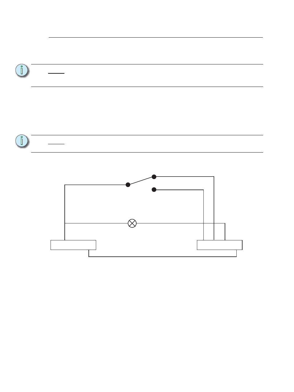
Wire the remote switch and indicator to the J12 connector according to
Figure 26.
N o t e :
You must supply your own enclosed single-pole double-throw center-off switch to
install a remote select switch. You may optionally use an external 24V DC power
supply, or use the power supply from the rack backplane.
N o t e :
The J12 connector is a removable plug header and is easier to wire when it is
disconnected from the backplane in an installed rack.
1 2 3 4
+24Vdc COM
J12
Figure 26: J12 Dual Tracking remote connector wiring
Header at the top of the
backplane PCB
Orange remote tracking header.
Pin 1 is the pin closest to the phase
bars (left side of the rack as you look
in)
Position A - Primary
Position B - Secondary
An indicator lamp
50mA 24Vdc max for
internal power supply