Finishing installation, Check backplane dip switches, Energising the system – ETC Sensor3 CE (ESR3) Rack User Manual
Page 35: Contacting etc
5
Finishing Installation
27
C h a p t e r 5
Finishing Installation
The steps in this chapter should only be performed by, or after receiving approval from, an
authorised ETC representative.
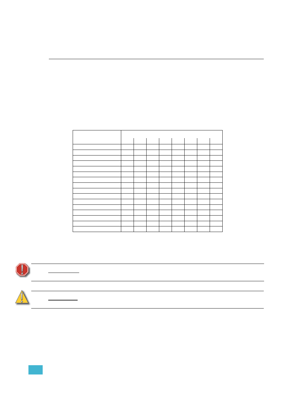
Check Backplane DIP Switches
The backplane of your rack features a set of eight DIP switches allowing configuration of
the rack type. The CEM3 reads these DIP switches to determine the rack type, phasing and
available modules. Compare the position of these DIP switches to the table below and, if
necessary, set them to the correct position using a jewellers screwdriver.
Use the following chart to determine your required DIP switch settings:
Energising the System
You need ETC approval to apply power to your dimming system. Wiring errors in
unauthorised installations may endanger operators or cause system damage and failure.
Contacting ETC
To obtain ETC approval or for referral to an authorised ETC representative, contact ETC
as shown in
.
DIP Switch Number
Rack Model
1
2
3
4
5
6
7
8
ESR3-12
On
On
ESR3-12N
On
On
On
ESR3-12AF
On
On
On
ESR3-12AFN
On
On
On
On
ESR3-24
On
On
ESR3-24N
On
On
On
ESR3-24AF
On
On
On
ESR3-24AFN
On
On
On
On
ESR3-36
On
On
ESR3-36N
On
On
On
ESR3-36AF
On
On
On
ESR3-36AFN
On
On
On
On
ESR3-48
On
ESR3-48N
On
On
ESR3-48AF
On
On
ESR3-48AFN
On
On
On
W A R N I N G :
Do not attempt to energise the system without proper approval. Energising
the system without ETC approval may result in serious injuries.
C A U T I O N :
Energising your system without ETC approval may result in equipment damage
that may void your warranty!