ETC Sensor3 CE (ESR3) Rack User Manual
Page 22
14
Sensor3 CE Rack (ESR3) Installation Manual
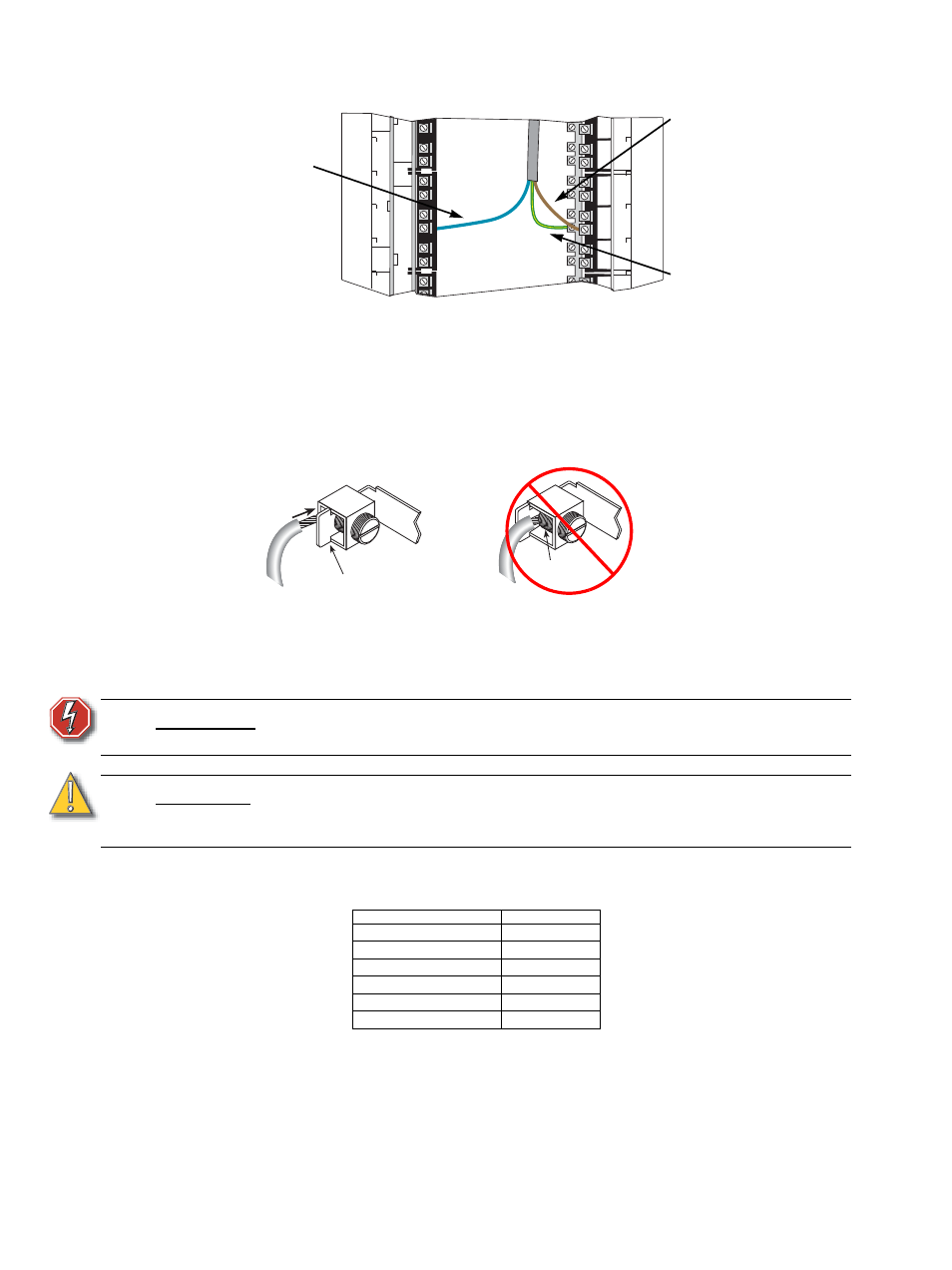
that phase, neutral and earth can be corrected to the relevant lugs as shown.
Step 3:
Fit load earth wires into the earth lugs as shown below and torque to the
recommended value from Table 1.
•
Insert the wire under the pressure plate and tighten it onto the wire with the
screw. Do not clamp the wire directly under the screw.
Figure 13: Connecting lug wires
Step 4:
Fit load neutral wires into the neutral lugs in the same manner and torque to the
recommended value.
Step 5:
Fit load phase wires into the phase lugs in the same manner and torque to the
recommended value.
Step 6:
Tighten all load connections to the torque specified in the table below.
Table 1: Lug torque values
W A R N I N G :
If any wire splices are required (none are recommended), they must be
made with a crimp-style butt-splice. Terminal block is NOT acceptable.
C A U T I O N :
To prevent interference with cooling airflow, do not run load wires from one rack
through a different rack. See
Sealing Rack Air Leaks, page 28
for more
information.
Cable size
Torque (Nm)
1.5mm
2
4.0 Nm
2.5mm
2
4.0 Nm
4.0mm
2
4.0 Nm
6.0mm
2
4.5 Nm
10mm
2
4.5 Nm
16mm
2
5.0 Nm
Figure 12: Load cable connection to lugs
Load Neutral (blue
wires) are landed on
load neutral lugs
attached to the main
neutral bus plate
Each dimmer’s load
lug set is at the same
height.
Load Phase
(brown wire)
Load Earth
(green wire with
yellow stripe)
The Right way
Insert the wire between the pressure plate and
the back of the lug and clamp the plate on top of
the wire.
The Wrong way
Don’t clamp the wire on top of the
pressure plate with the lug screw.
Pressure Plate
Lug Screw