Fan not working, Data loss – ETC Matrix MkII Rack User Manual
Page 26
Matrix Mk.II Rack Installation Manual
Fan not working
With Matrix II, the ventilation fans are located in each module. They are activated only when the
module reaches a pre-set internal temperature of 35degC, and they increase in speed in proportion to
the amount of heat present. To check the operation of the fan, depress the test button on the module
for about 5 seconds, after which time the fan will switch on. If it does not switch on, the fan may need
replacing.
Data loss
Data loss at the processor
No data present at the processor is displayed on the processor panel by an X
against the DMX legend. If this is the case, test the output from the control system
through any intermediary buffers, routers or switches.
If the data is correct, disconnect power from the rack and at the rear of the
processor swap the connections between inputs 1 and 2 (Ethernet 1 and 2 or DMX
1 and 2 depending on the data used) to see if the problem can be traced to the
different internal processing routes. If the data signal appears on the alternative
channel, the problem may be in the processor. If the second input does not
respond to the data signal, there is a problem with the data wiring to the rack.
Data loss at a single module
In the first instance, simply exchange the module with no data with an adjacent
module of the same type to check if the replacement responds to data. If it does,
the module is at fault. Check the module’s data cable (flat ribbon cable) to make
sure it is not damaged and is firmly located in its socket.
Data loss at a row or column of modules
If data is present at the processor but one row of modules has lost data, the
problem may be with the data connection PCB which is accessible from the rear of
the rack. Data is connected vertically through the rack via a ribbon cable, so in the
first instance check that the cable connection is correctly made and the ribbon
cable is locked in place.
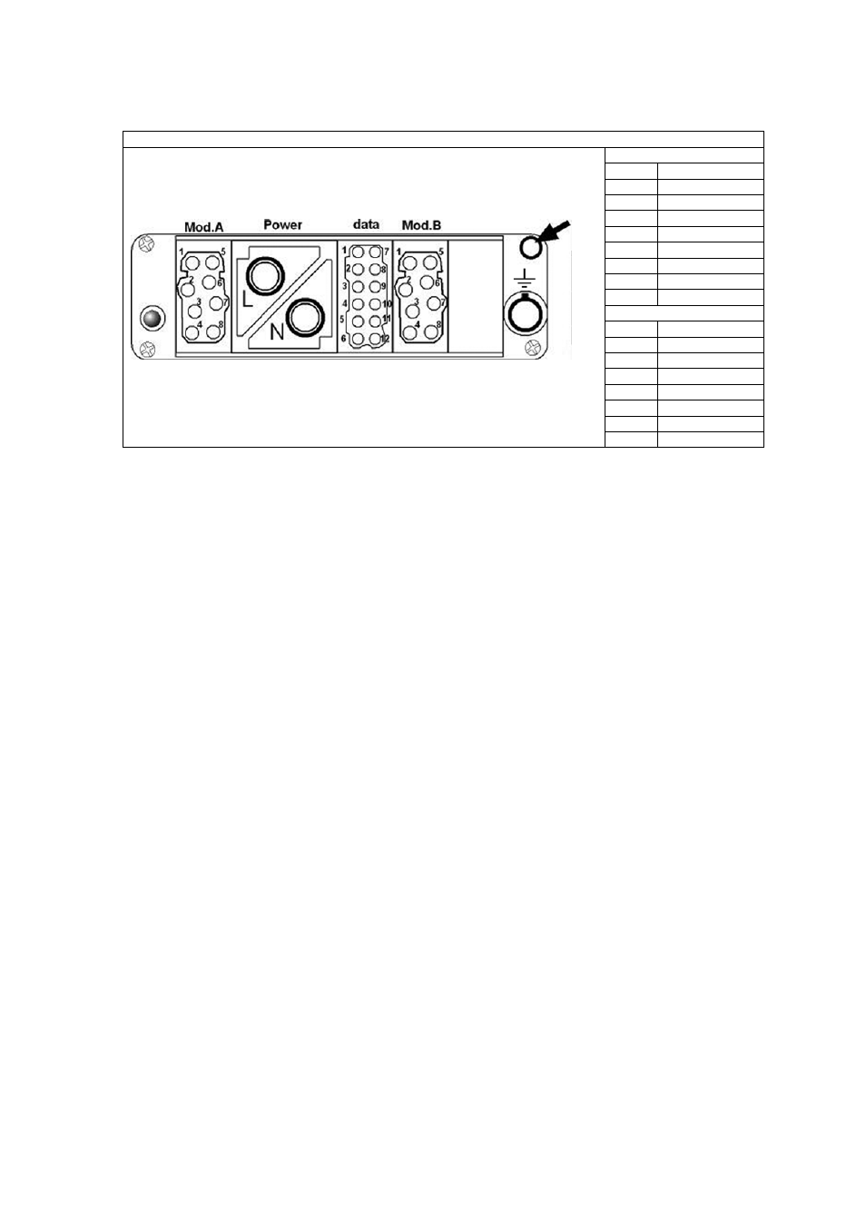
Multipin socket for 4 x 5kW module (Custom 32A and standard 63A/12kW modules)
Multipin socket showing the position of the standoff pillar (arrowed) and pin numbering.
Note that Mod A and Mod B are paralleled.
Mod. A
Pin
Connection
1
Ch 1 - L
2
Ch 2 - L
3
Ch 3 - L
4
Ch 4 - L
5
Ch 1 - N
6
Ch 2 - N
7
Ch 3 - N
8
Ch 4 - N
Mod. B
1
Ch 1 - L
2
Ch 2 - L
3
Ch 3 - L
4
Ch 4 - L
5
Ch 1 - N
6
Ch 2 - N
7
Ch 3 - N
8
Ch 4 - N