Installing the station into the backbox, Unison paradigm wireless access station – ETC Unison Paradigm Wireless Access Station User Manual
Page 3
E T C I n s t a l l a t i o n G u i d e
Unison Paradigm Wireless Access Station
Unison Paradigm Wireless Access Station
Page 3 of 4
Electronic Theatre Controls, Inc.
d:
Close the levers onto the wires.
e:
Repeat for the installed (typically red) 16 AWG (1.5 mm
2
) Auxiliary Power
wire and remaining pigtail wire using a new WAGO connector.
f:
Install the Auxiliary connector onto the Wireless Access Station control
board.
Step 4: Terminate the ESD drain (ground) wire.
a:
Locate the ground wire pigtail and one
WAGO connector from the termination kit.
b:
Strip 3/8” (9-10 mm) from the end of each
ground wire (both the provided pigtail and the
installed wire).
c:
Use the WAGO connector to connect the
installed ground wire to the pigtail wire
provided. Open the terminal levers on the
WAGO connector and insert the installed
(typically green/yellow) ESD drain (ground)
wire and the green/yellow lead from the
pigtail into the terminals.
d:
Close the levers onto the wires.
e:
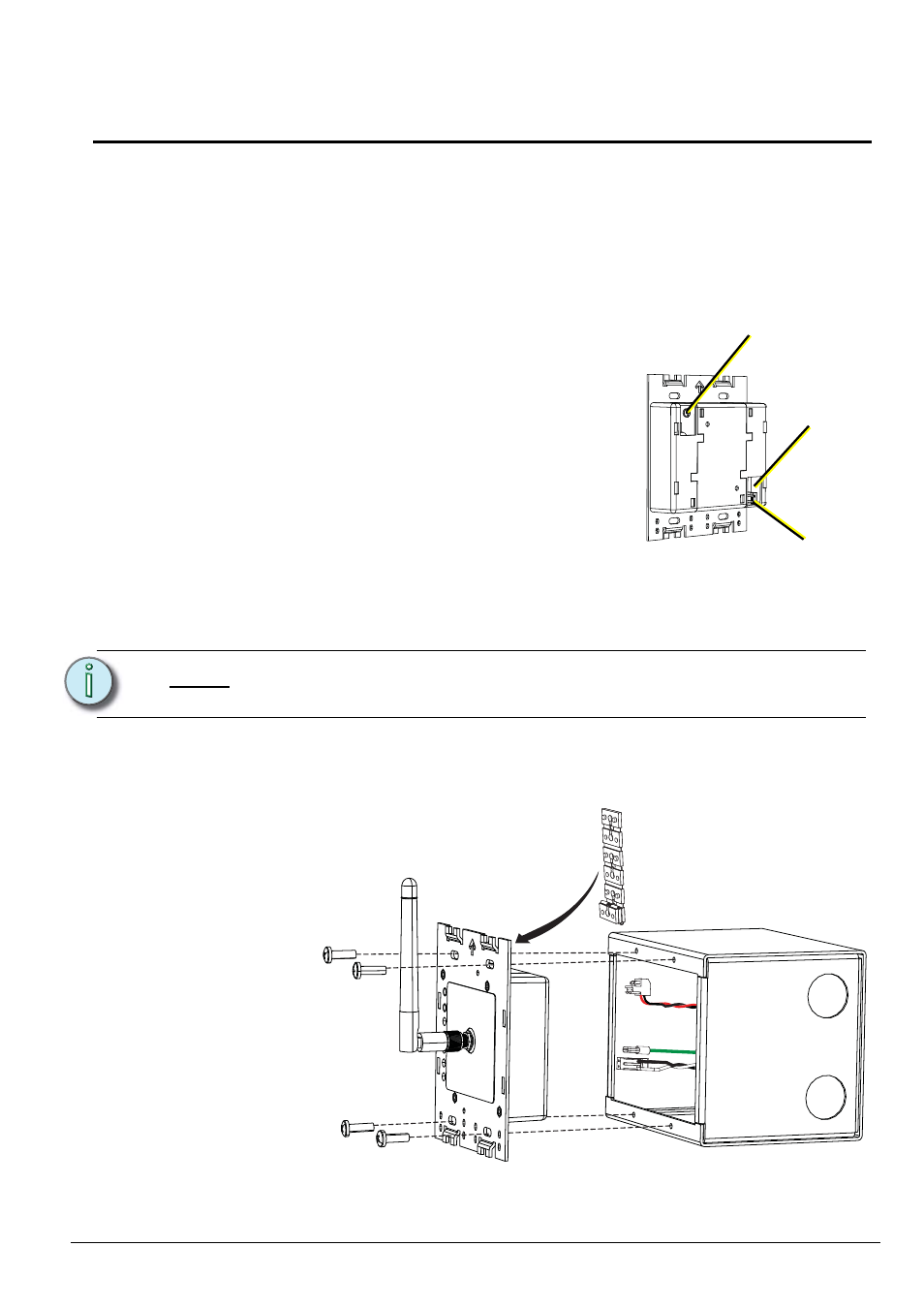
Install the ground spade onto the receptacle on the station electronics.
Installing the Station into the Backbox
Spacers are provided to help align the station and cover flush against the wall in flush
mount applications.
N o t e :
All stations must be grounded using or a 14 AWG (2.5 mm
2
) ESD drain wire or
continuous runs of grounded metal conduit.
Ground
Spade
LinkPower
connector
Auxiliary Power
connector
Step 1: Insert the station electronics and wiring into
the backbox. The arrow on the mounting
plate must point up.