Installing the wireless access station, Connect the wiring, Unison paradigm series – ETC Unison Paradigm Wireless Access Station User Manual
Page 2
E T C I n s t a l l a t i o n G u i d e
Unison Paradigm Series
Unison Paradigm Wireless Access Station
Page 2 of 4
Electronic Theatre Controls, Inc.
Installing the Wireless Access Station
The backbox should be installed square for best results. Ensure that the backbox is
clean and free of obstructions and that all wiring is installed correctly.
Wireless Access Stations ship with a termination kit including a LinkConnect pigtail,
Auxiliary Power pigtail, ground wire pigtail, spacers and the required connectors for
installation.
Connect the Wiring
Step 1: Pull all required wiring to the installed backbox.
Step 2: Terminate and connect LinkPower. LinkPower is topology free and polarity
independent. You may install LinkPower in any combination of bus, star, loop
or home-run.
a:
Locate the LinkPower pigtail and two WAGO CAGE CLAMP
®
connectors
from the termination kit.
b:
Strip 3/8” (9-10 mm) from the ends of each LinkPower wire (both pigtail
and installed LinkPower wires).
c:
Use the WAGO connector to connect the installed control wire to the
connectorized pigtail wires provided. Open the terminal levers on the
WAGO connector and insert the installed (typically black) Belden 8471
LinkPower wire and the black lead from the LinkPower pigtail into the
terminals.
d:
Close the levers onto the wires.
e:
Repeat for the installed (typically white) Belden 8471 LinkPower wire and
remaining pigtail wire using a new WAGO connector.
f:
Install the LinkPower connector onto the Wireless Access Station control
board.
Step 3: Terminate and connect the Auxiliary Power (24 Vdc) wiring.
a:
Locate the Auxiliary Power pigtail and two WAGO connectors from the
termination kit.
b:
Strip 3/8” (9-10 mm) from the ends of each Auxiliary wire (both pigtail and
installed wires).
c:
Use the WAGO connector to connect the installed power wire to the
connectorized pigtail wires provided. Open the terminal levers on the
WAGO connector and insert the installed (typically black) 16 AWG
(1.5 mm
2
) Auxiliary Power wire and the black lead from the pigtail into the
terminals.
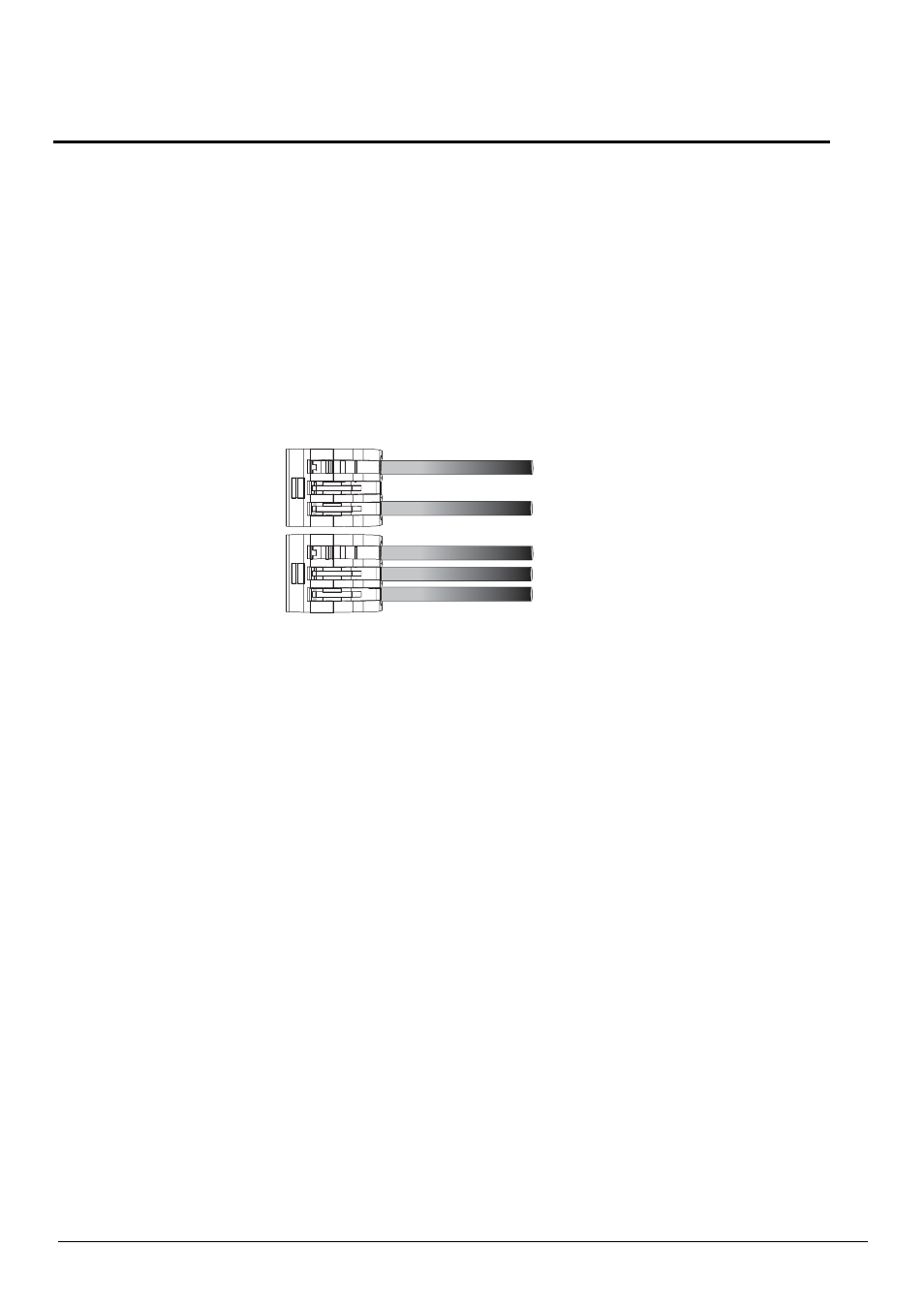
Topology of a
single station
installation
Topology of
multiple stations
installed in series
Installed control wire
Pigtail wire
Installed control wire
Installed wire to next station
Pigtail wire