Addenda, B-series sleeve repair – ERICO CADWELD for Rebar Splicing System User Manual
Page 15
13
www.erico.com
Addenda
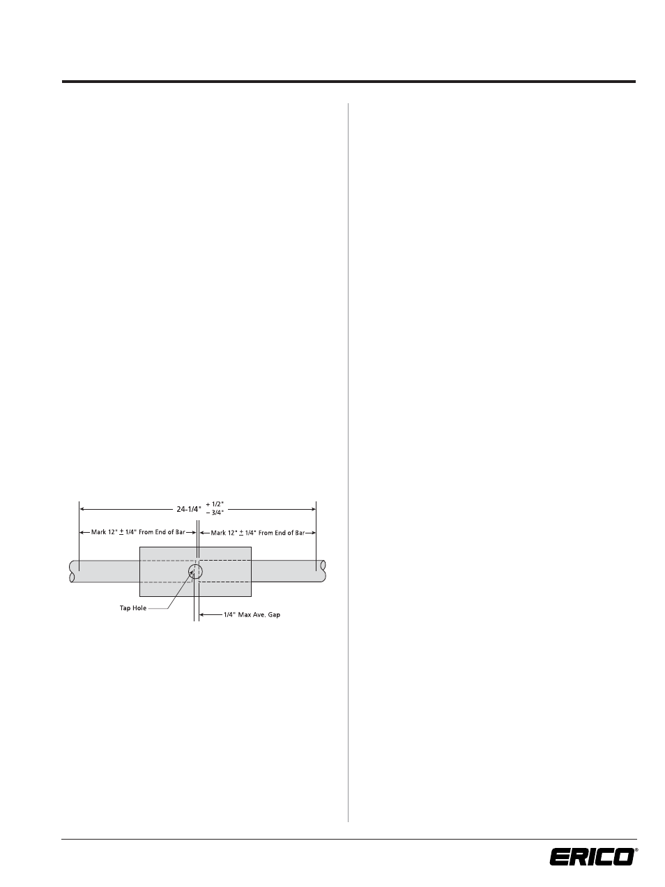
External Bar Reference Marks
Each bar should be marked some known distance from the
end to provide an external means of checking the location of
the bar ends within a completed splice. Any convenient dis-
tance may be used so long as the marks are visible outside of
the splice sleeve. As an example, we have used the dimension
of 12 in. (30.5 cm).
For inspection purposes, we recommend a plus or minus toler-
ance of 1/4-in. (6 mm) on each reference mark.
To prevent damage to the bar, we recommend using either
permanent ink or paint as a marking material, blunt nose
punch or draw file at the option of the engineer. Do not use
prick punch or chisel.
Using our recommendations, the procedure would be as
follows:
1. Prior to making the splice, an external reference mark shall
be applied to each bar at a distance of 12 in. (30.5 cm) plus
or minus 1/4-in. (6 mm) from the end of the reinforcing bar.
2. After the splice is completed, the distance between external
reference marks shall not exceed 24
3
/
4
-in. (62.9 cm).
3. The midpoint of the distance between external reference
marks shall lie within the diameter of the sleeve tap hole.
NOTE: When distance between reference marks is less than
23
1
/
2
-in. (59.7 cm), marks may not be within tolerance.
A random check on reference mark locations should
be made.
Bar End Gap
If a natural gap is not provided by the shape of the reinforcing
bar ends, such as the tapered nature of shear cut bar ends or
the tapered and uneven surface of flame cut ends, a spacer
can be used to obtain a 3/16-in. (5 mm) to 1/4-in. (6 mm)
average gap between the bar ends. An average gap is not
restricted to a uniform gap.
In the horizontal position, a spacer can be used to set the
average gap and then it can be removed. The spacer is not
required to remain in position.
In the vertical position, when a natural gap is not formed by
the shape of the reinforcing bar ends, a spacer may be used to
provide a gap.
B-Series Sleeve Repair
Piggy-Back Repair
Repair of low filled structure splices can be accomplished by
stacking or “Piggy-Backing” a second sleeve on to the end of
the original sleeve. Depending upon construction conditions,
the piggy-back sleeve may be a standard bar-to-bar splice
sleeve, standard J-Groove structure splice sleeve, split bar-to-
bar splice sleeve, or a split J-Groove structure splice sleeve.
(Please see sketches on page 14.)
The principle behind the use of a bar-to-bar splice sleeve as
the piggy-back repair is to completely fill the void in the initial
sleeve and the new sleeve. Doing this only requires the use
of a tack weld between sleeves. However, the filler metal
cartridge must be adjusted each time to allow for the extra
volume created by the voids in the initial splice.
The use of a J-Grooved structure splice sleeve enables the
voids in the initial splice to be packed with inert packing
material, eliminating having to calculate the void areas and
adjusting the filler metal cartridge accordingly. A standard
cartridge can be used each time. However, a structural weld
between the initial and piggy-back sleeve is required to trans-
mit the tension stress from the repair sleeve through the initial
sleeve and into the structural plate or shape.
When it is not possible to slide a new sleeve over the loose
end of the reinforcing bar, a split sleeve can be placed around
the reinforcing bar and welded together forming a closed
sleeve. This can be done using either a split bar-to-bar or a
split structure splice sleeve, depending on which method of
repair is used. When welding the split sleeve, care should be
taken to prevent striking an accidental arc on the reinforcing
bar.