Specifications – Det-Tronics R7495D UV/IR Flame Detection System User Manual
Page 7
various faults that could prevent the system from
responding in the event of a fire. If a fault is detected:
1. The normally energized fault relay is de-energized.
This relay can be used to activate an external fault
annunciation device or to remove power from a haz-
ardous process.
2. The FAULT LED on the front panel of the controller
is illuminated to provide a visual indication that a
problem has occurred.
Programming Switches
Rocker switches that are located on the side of the con-
troller are used for selecting various options available
with the R7495D. These programming options are listed
below and must be set prior to system operation. Refer
to the “Programming the Controller” section of this man-
ual for detailed instructions.
1. Number of detectors connected to the controller
(one or two).
2. Gate Length, Consecutive Gate Selection, Count
Selection (system sensitivity and time delay).
3. Fire zone grouping.
4. Latching/non-latching outputs.
Field Wiring Connector
The R7495D Controller is furnished with a field wiring
connector that incorporates pressure type screw termi-
nals for connecting the external wiring. The use of a
Q4004 Mounting Cage is recommended for mounting
the controller. The controller is designed for installation
in a non-hazardous area.
SPECIFICATIONS
SPECTRAL SENSITIVITY RANGE—
UV: The UV sensor responds to radiation over the range
of 0.185 to 0.245 microns (1850 to 2450
angstroms).
IR: The single frequency infrared sensor responds to
radiation between 4.2 and 4.7 microns.
Figure1 illustrates the spectral response range of the UV
and IR sensors.
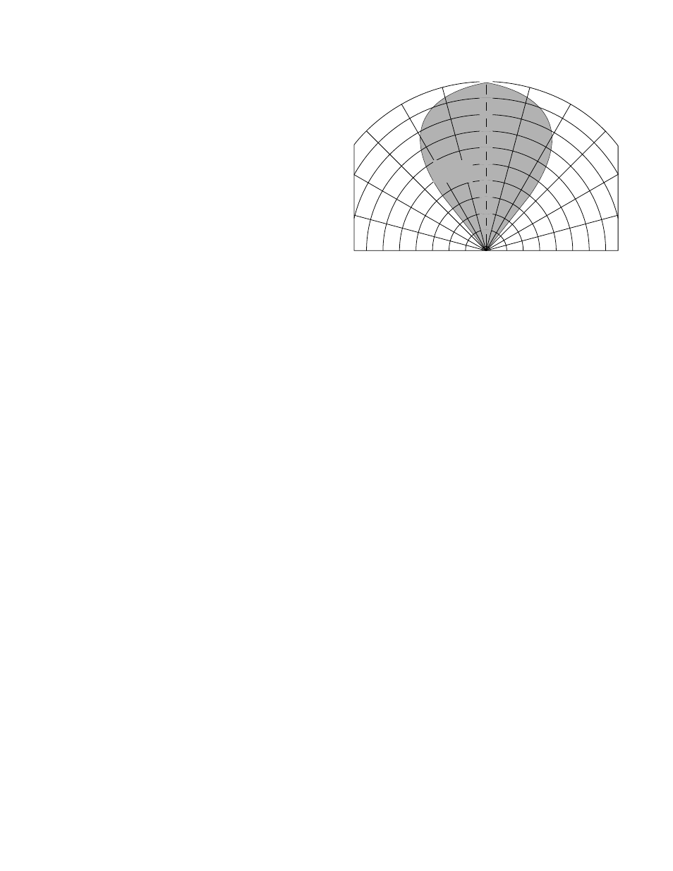
CONE OF VISION—
The C7052J has a 80 degree cone of vision with the
highest sensitivity lying along its central axis. See
Figure 4.
FLAME SENSITIVITY—
The C7052J5 with a part number DE5500 IR Sensor
Module (the sensor part number is printed on its side)
detects a 1 foot by 1 foot gasoline fire at 50 feet, a 2 foot
by 2 foot JP4 fire at 100 feet, and a 10 foot by 10 foot
JP4 fire at 150 feet.
The C7052J with a part number DE3895 IR Sensor
Module (the sensor part number is printed on its side)
detects a 1 foot by 1 foot gasoline fire at 35 to 45 feet, a
2 foot by 2 foot JP4 fire at 100 feet, and a 10 foot by 10
foot JP4 fire at 150 feet.
RESPONSE TIME—
The response time of the detector is a function of fuel,
fire size, distance, orientation of the fire source and the
field programmable controller settings. With typical
controller settings of 0.25 second gate length, 4 counts
per gate, and 4 consecutive gates, the system will
respond to an intense fire signal in less than 2 seconds.
Response times of less than 1 second to an intense fire
signal can be achieved by setting the controller for a
0.125 second gate length, 2 counts per gate, and 3
consecutive gates.
INPUT VOLTAGE—
Controller and Detector
24 vdc nominal (18 vdc minimum, 32 vdc maximum)
with less than 1 volt of ripple.
POWER CONSUMPTION—
Controller:
1.0 watt typical, 3.5 watts maximum.
Detector:
1.0 watt typical, 3.5 watts maximum.
RELAY CONTACT RATING—
Five form C (NO/NC) relay outputs, rated 3 amperes at
up to 30 vdc or up to 250 vac. Dry nitrogen gas is
0°
15°
30°
45°
15°
30°
45°
A1461
100
90
80
70
60
50
40
30
20
10
DETECTION
DISTANCE
(PERCENT)
100% REPRESENTS THE MAXIMUM DETECTION DISTANCE FOR A
GIVEN FIRE. THE SENSITIVITY INCREASES AS THE ANGLE OF
INCIDENCE DECREASES.
7
95-8331
Figure 4—Cone of Vision