Det-Tronics R7495D UV/IR Flame Detection System User Manual
Page 19
STAR Logic Programming (System Sensitivity and
Time Delay) - Rocker Switches 2-1 to 2-8 (Gate
Length), Rocker Switches 3-1 to 3-4 (Count Selection
Per Gate), and Rocker Switches 3-5 to 3-8
(Consecutive Gates Selection).
The STAR Logic switch settings determine system sen-
sitivity and time delay. The most important factor in
determining the appropriate sensitivity setting for a par-
ticular application is the intensity of radiation expected
to reach the detector in the event of a fire. This
depends on several factors, including the distance of
the detector from the potential fire, the fuel type, the
flame size, and whether any radiation absorbing vapors
are present (these are listed in Table 2).
The most effective way to set system sensitivity is to
install the system, program the STAR Logic according
to the typical settings shown in Figure 21, program all
other aspects of controller operation according to this
section (“Programming the Controller”), then perform
the “Initial and Periodic Checkout Procedure” using a
UV/IR test lamp and the “STAR Programming Checkout
Procedure.” If the system fails to respond appropriately
during these tests and all system wiring is correct, then
system sensitivity (gate length, counts per gate, and
consecutive gates) needs to be adjusted. It is important
that all wiring and programmed settings be checked to
ensure that they are correct before adjusting these set-
tings.
Rocker switch assemblies 2 and 3 control three variables:
gate length, counts per gate and consecutive gates
required for a fire output. Refer to Figure 21 for a visual
representation of how these variables function together
with typical controller settings. Keep in mind that when
the UV and IR sensors of the detector respond to a fire,
the IR sensor activates the circuitry in the UV/IR detector
junction box. This allows the electrical pulses (signal)
from the UV sensor to be sent to the controller. The fre-
quency of this signal is proportional to the intensity of the
fire. The controller looks at this signal in comparison to
the sensitivity settings in order to determine whether a fire
exists. A brief description of each variable follows:
1. Gate Length is adjustable from 31.25 milliseconds
to 8 seconds. The gate length is the increment of
time that the controller looks at the detector signal
to determine if the “Counts per Gate” requirement is
fulfilled. In Figure 21, the gate length is 0.25 sec-
onds (Rocker Switch 2-4 closed, Rocker Switches
2-1, 2-2, 2-3, 2-5, 2-6, 2-7, and 2-8 open).
2. Counts per Gate is adjustable from 2 to 15 counts.
These counts make up the signal from the detector
and are a direct response to a flame or other UV/IR
source. In Figure 21, the counts per gate setting is
4 counts (Rocker Switch 3-3 closed, Rocker
Switches 3-1, 3-2, and 3-4 open).
3. Consecutive Gates required for a fire output are
adjustable from 2 to 15 gates. This is the number of
consecutive gates in which the “Counts per Gate”
requirement is fulfilled that the controller must see
before going into a fire alarm condition. In Figure
21, the consecutive gates setting is 4 gates (Rocker
Switch 3-7 closed, Rocker Switches 3-5, 3-6, and 3-
8 open).
19
95-8331
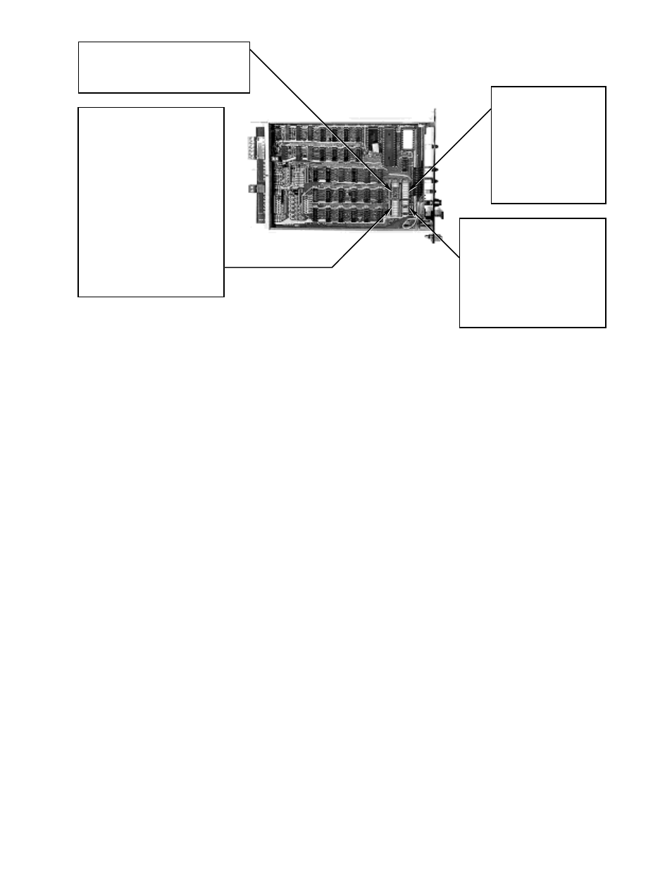
Figure 20—Rocker Switch Setting
B1053
SWITCH ASSEMBLY 3
COUNT SELECTION
CLOSE ROCKERS TO ACTIVATE
ROCKER 1 – 1 COUNT
ROCKER 2 – 2 COUNTS
ROCKER 3 – 4 COUNTS
ROCKER 4 – 8 COUNTS
VALUES OF ROCKERS CLOSED
ARE ADDED TOGETHER – 2 COUNTS MINIMUM
IF GATE IS GREATER THAN OR EQUAL
TO 0.5 SECOND, A MULTIPLICATION FACTOR
MUST BE USED.
CONSECUTIVE GATE SELECTION
CLOSE ROCKERS TO ACTIVATE
ROCKER 5 – 1 GATE
ROCKER 6 – 2 GATES
ROCKER 7 – 4 GATES
ROCKER 8 – 8 GATES
VALUES OF ROCKERS CLOSED
ARE ADDED TOGETHER – 2 GATES MINIMUM
SWITCH ASSEMBLY 2
GATE LENGTH
CLOSE ROCKERS TO ACTIVATE
VALUES OF ROCKERS CLOSED
ARE ADDED TOGETHER
ROCKER SWITCH NUMBERS ARE DESIGNATED 1-1, 1-2, 1-3, ETC.
THE NUMBER PRECEDING THE DASH INDICATES THE SWITCH ASSEMBLY.
THE NUMBER FOLLOWING THE DASH INDICATES THE ROCKER NUMBER.
NOTE 1:
DEPRESS ROCKER TOWARD "OPEN" ON SWITCH ASSEMBLY TO SET IN THE OPEN POSITION.
DEPRESS ROCKER TOWARD NUMBER DESIGNATIONS TO SET IN CLOSED POSITION.
NOTE 2:
SWITCH ASSEMBLY 4
FIRE ZONES
ROCKER 1 –
INDIVIDUAL RESPONSE
WHEN ROCKER IS CLOSED,
COMBINED WHEN ROCKER IS OPEN.
OUTPUTS LATCHING
ROCKER 5 –
LATCHING OUTPUTS WHEN ROCKER IS OPEN
ROCKERS 2 AND 6 NOT USED
SWITCH ASSEMBLY 1
DETECTOR SELECTION SWITCH
PLACE ROCKER IN OPEN POSITION
FOR EACH CHANNEL WITH A DETECTOR CONNECTED
ROCKER 1 – 31.25 MILLISECONDS
ROCKER 2 – 62.5 MILLISECONDS
ROCKER 3 – 0.125 SECOND
ROCKER 4 – 0.25 SECOND
ROCKER 5 – 0.5 SECOND
ROCKER 6 – 1 SECOND
ROCKER 7 – 2 SECONDS
ROCKER 8 – 4 SECONDS