Det-Tronics R7495D UV/IR Flame Detection System User Manual
Page 20
If changes in the sensitivity and/or time delay settings
are required, read the detailed discussions of each of
the three STAR Logic variables that follows before mak-
ing changes. When changing the settings, keep in
mind the following guidelines:
1.
Increasing Gate Length while the other variables
remain unchanged results in higher sensitivity and a
longer time delay.
2.
Increasing Consecutive Gates while the other vari-
ables remain unchanged results in a longer time
delay and greater noise rejection.
3.
Increasing Counts per Gate while the other vari-
ables remain unchanged results in lower sensitivity
and more false alarm resistance.
Gate length - Rocker Switches 2-1 to 2-8
The gate length can be adjusted in 31.25 millisecond
increments from 31.25 milliseconds to 8 seconds. Each
rocker selects a particular time value. The gate length
is the value of all rockers closed, added together. If no
rocker is closed, the controller will select the minimum
length (31.25 milliseconds). The typical gate length set-
tings used in most applications are between 0.125 and
0.5 second.
Rocker 2-1 - 31.25 milliseconds
Rocker 2-2 - 62.5 milliseconds
Rocker 2-3 - 0.125 second
Rocker 2-4 - 0.25 second
Rocker 2-5 - 0.5 second
Rocker 2-6 - 1 second
Rocker 2-7 - 2 seconds
Rocker 2-8 - 4 seconds
The value of the closed switches are added together to
obtain the total time delay.
Count Selection - Rocker Switches 3-1 to 3-4
When a gate length of less than 0.5 second is used, the
rockers select counts needed per gate for a fire signal.
The values of all rockers closed are added together. If
no counts or less than 2 counts are selected (only rock-
er 1 closed), the microprocessor will select 2. Counts
per gate are selectable in 1 count increments from 2 to
15 counts. The typical counts per gate setting used in
most applications are between 2 and 8 counts.
Rocker 3-1 - 1 count
Rocker 3-2 - 2 counts
Rocker 3-3 - 4 counts
Rocker 3-4 - 8 counts
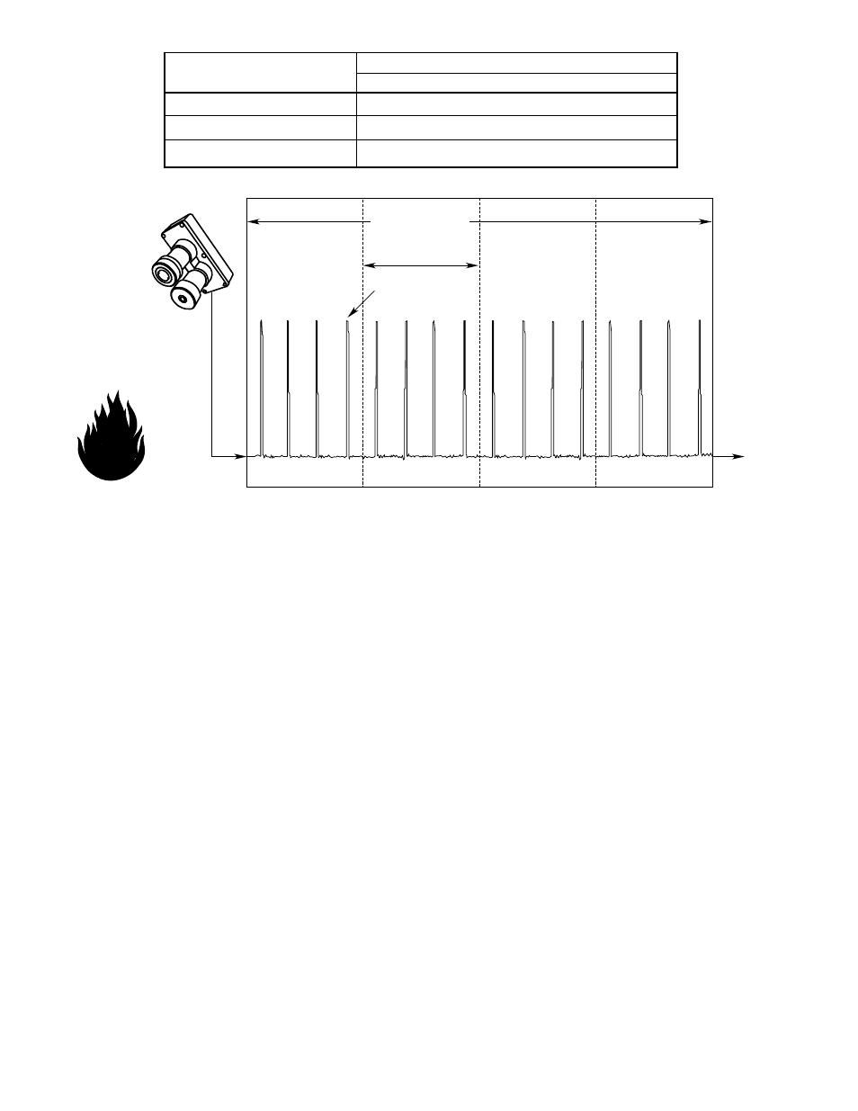
SIGNAL
FLAME
C7052J
STAR LOGIC (TYPICAL SETTINGS SHOWN)
CONTROLLER
ALARM
CONDITION
COUNT (SIGNAL)
4 COUNTS PER GATE
4 CONSECUTIVE GATES
0.25 SECOND GATE LENGTH
A1708
Figure 21—Graphic Representation of STAR Logic (Typical Settings Shown)
20
R7495 STAR Logic Program
4 Counts per Gate
0.25 Second Gate Length
4 Consecutive Gates
R7495 Switch Settings
Rockers Closed
Rockers Open
3-3
3-1, 3-2, 3-4
2-4
2-1, 2-2, 2-3, 2-5, 2-6, 2-7, 2-8
3-7
3-5, 3-6, 3-8