Det-Tronics R7495D UV/IR Flame Detection System User Manual
Page 10
Potential radiation sources in the environment must also
be carefully considered. A UV sensor will respond to
sources of UV besides fire, such as electric arc welding,
lightning, x-rays and gamma radiation. The C7052J has
been designed to ignore steady state infrared sources
that do not have a flicker frequency characteristic of a
fire, however, it should be noted that if these steady
state infrared sources are hot enough to emit adequate
amounts of infrared radiation in the response range of
the IR sensor and if this radiation becomes interrupted
from the view of the detector in a pattern characteristic
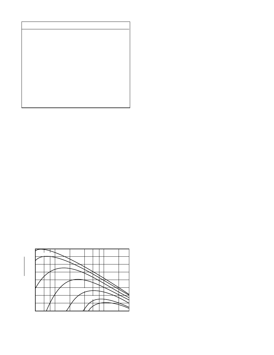
of a flickering flame, the IR sensor can respond. Any
object having a temperature greater than 0° Kelvin
(–273°C) emits infrared radiation. The hotter the object,
the greater the intensity of the emitted radiation. See
Figure 9. The closer the infrared source is to the detec-
tor, the greater the potential for the IR sensor to produce
an alarm. The IR sensor can respond to IR radiation
sources that can meet the amplitude and flicker require-
ments of the detector such as vibrating hot objects.
Although the C7052J Detector is designed to reduce
false actuations, certain combinations of ambient radia-
tion must be avoided. For example, if IR radiation with
an intensity that exceeds the fire threshold of the IR sen-
sor should reach the detector as a flickering signal, and
if at the same time an electric arc welding signal also
reaches the sensors, an alarm output will be generated.
The C7052J ignores arc welding beyond 15 feet from
the detector. However, the UV sensor will respond to
the intense UV radiation generated by the arc welding,
and at distances closer than 15 feet the heated metal
from the welding can become a false alarm source for
the IR sensor.
Another important fact regarding a radiation detector of
any type is that radiation must reach the detector in
order for it to respond. Care must be taken to keep
physical obstructions out of the line of view of the detec-
tor. In addition, UV or IR absorbing gases or vapors
must not be allowed to accumulate between the detec-
tor and the protected hazard. See Table 2 for a listing
of these substances. Smoke will also absorb radiation,
therefore, the detector should not be mounted close to
the ceiling or other areas where smoke can accumulate.
It is important to keep the detector viewing windows as
free of contaminants as possible in order to maintain
maximum sensitivity and to assure proper operation of
the flame detection system. Commonly encountered
substances that can significantly attenuate UV and/or IR
radiation include, but are certainly not limited to, the fol-
lowing:
Silicones
Oils and greases
Ice buildup
Dust and dirt buildup
Paint overspray
The oi test feature is designed to register an oi fault
when the detector sensitivity is reduced to approximate-
ly 50% of its maximum detection range. For maximum
system reliability, it is recommended that the detector
viewing windows be cleaned on a regularly scheduled
basis. (Refer to the “Maintenance” section of this manu-
al for additional information regarding detector mainte-
nance.) The use of model Q1113 Air Shields can help
extend the time period between required maintenance.
The C7052J is designed to be resistant to interference
from EMI and RFI. It will not respond to a 5 watt walkie-
talkie at a distance of greater than 1 foot.
The C7052J uses a single frequency IR sensing device
with detection limited to the hot CO2 emission peak,
therefore, it cannot be used to detect fires that do not
contain carbon, such as hydrogen, sulfur, burning met-
als, or other non-hydrocarbons without thorough testing.
10
Table 1—C7052J Typical Response Distances
Fuel
Distance from C7052J5
Acetone
45 feet (13.7 meters)
Diesel
40 feet (12.2 meters)
Gasoline
50 feet (15 meters)
JP4 (surface area)
2 ft2
100 feet (30 meters)
4 ft2
150 feet (45 meters)
10 ft2
150 feet (45 meters)
Methane
35 feet (10.7 meters)
Methanol
35 feet (10.7 meters)
Wood Shavings (Excelsior)
50 feet (15 meters)
Wood Stack (Crib)
50 feet (15 meters)
Figure 9—Blackbody Spectral Emittance
10
4
10
3
10
2
10
1
1
10
–1
10
–2
10
–3
10
–4
0.4
0.6
0.8
1
2
4
6
8 10
20
30
RADIANT EMITTANCE
WATTS
(CM ) (MICRON)
2
WAVELENGTH (MICRONS)
6000
°
K
2000
°
K
250
°
K
500
°
K
300
°
K
4000
°
K
1000
°
K
A0576