Startup procedure – Det-Tronics R7495D UV/IR Flame Detection System User Manual
Page 22
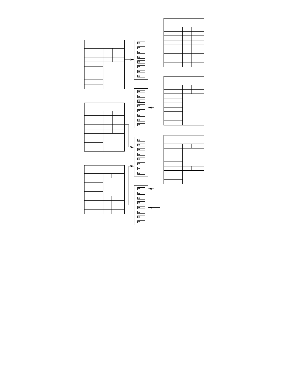
Figure 24 shows power connected to a load circuit
through the normally closed contacts of the Alarm relay.
When a “fire” signal is received by the controller, the
contacts open, removing power from the load.
Power is connected to a process or system control cir-
cuit through the normally closed contacts of the Fault
relay. When a system fault occurs or when the con-
troller is in the Test mode, the contacts open, removing
power from the process. An alarm circuit is connected
to the power source through the normally open contacts
of the Fault relay. When a system fault occurs, the con-
tacts close, powering the alarm.
Figure 25 depicts a similar output circuit, with a normally
unenergized load connected to the Fire relay.
STARTUP PROCEDURE
The startup procedure should be performed after instal-
lation of the equipment is complete.
1. After making the electrical connections and setting
the switches, plug the controller into the wiring con-
nector.
2. Disable any extinguishing system connected to the
system.
3. Turn on the input power to the system and perform
the “Initial and Periodic Checkout Procedure.”
4. If the controller is operating normally and is pro-
grammed correctly, remove any mechanical block-
ing devices and restore power to the extinguishing
loads.
22
SWITCH 1
DETECTOR SELECT
SWITCH 3
CONSECUTIVE GATE
SELECTION
SWITCH 3
COUNT SELECTION
SWITCH 2
GATE LENGTH (SECONDS)
SWITCH 4 - 5
OUTPUTS LATCHING
SWITCH 4 - 1
FIRE ZONES
ROCKER
OPEN CLOSED
ROCKER
OPEN CLOSED
ROCKER
OPEN CLOSED
ROCKER
OPEN CLOSED
ROCKER
OPEN CLOSED
ROCKER
OPEN CLOSED
1
2
3
4
5
6
7
8
1
2
3
4
5 – 1 GATE
6 – 2 GATES
7 – 4 GATES
8 – 8 GATES
1 (1 COUNT)
2 (2 COUNTS)
3 (4 COUNTS)
4 (8 COUNTS)
5
6
7
8
1
2
3
4
5
6
7
8
1
2
3
4
5
6
7
8
1 – 0.031
2 – 0.062
3 – 0.125
4 – 0.25
5 – 0.5
6 – 1.0
7 – 2.0
8 – 4.0
1
2
3
4
5
6
7
8
OPEN SWITCH FOR EACH
DETECTOR CONNECTED
ADD VALUE OF CLOSED
ROCKERS – 2 GATES MINIMUM
ADD VALUE OF CLOSED
ROCKERS – 2 COUNTS MINIMUM
– USE MULTIPLICATION FACTOR
IF GATE IS 0.5 SECOND OR GREATER
ADD VALUE OF
CLOSED ROCKERS
OPEN = LATCHING
OPEN
B0994
1
2
3
4
5
6
7
8
OPEN
1
2
3
4
5
6
7
8
OPEN
1
2
3
4
5
6
7
8
OPEN
OPEN = COMBINED RESPONSE
CLOSED = INDIVIDUAL RESPONSE
Figure 23—System Layout Chart