Initial and periodic checkout procedure, Maintenance – Det-Tronics R7495D UV/IR Flame Detection System User Manual
Page 23
INITIAL AND PERIODIC CHECKOUT
PROCEDURE
The entire system should be periodically checked with a
UV/IR test lamp to be sure that the detectors are not
obstructed, that the area “seen” by the detector has not
changed, and that there is no fault in the oi circuit.
1. Place the Mode switch in the TEST position. The
FAULT LED will turn on.
CAUTION
Placing the controller in the Test mode inhibits the
outputs, rendering the system incapable of actuat-
ing any extinguishing or alarm circuits that are con-
nected to it. However, for maximum safety, secure
the output loads that would normally be actuated
by the system before performing the checkout pro-
cedure.
2. Shine the UV/IR test lamp into the viewing window
of the detector under test. The corresponding
DETECTOR LED flashes rapidly to identify the
detector under test.
If the requirements are met, the appropriate ALARM
LED and FIRE ZONE LED are also illuminated.
3. Turn off the UV/IR source. If turned on, the ALARM
LED and FIRE ZONE LED(s) continue to flash if
latching outputs are selected and are on steady if
not selected. The DETECTOR LED is on steady.
4. Repeat steps 2 and 3 for the other detector in the
system.
5. After all detectors have been checked, reset the
system by placing the Mode switch in the NORMAL
position. All LEDs except the POWER LED are off.
6. Restore power to the output loads and remove any
mechanical blocking devices.
STAR PROGRAMMING CHECKOUT PROCEDURE
1. Secure output loads (remove power from valves,
relays or other devices that might otherwise be
actuated by the UV/IR system) before testing.
2. Apply power to the UV/IR detection system.
3. Ensure that the area being monitored is operating
under normal conditions (equipment that would nor-
mally be on is on).
4. Place the UV/IR controller keyswitch in the NOR-
MAL position and monitor for one hour.
— If the rockers have been set correctly, transient
radiation in the area should not activate the system.
The upper and lower LED displays should remain
dark. If this is the case, lower (more sensitive) set-
tings can be attempted.
— If the system sensitivity is set too high, one of the
two DETECTOR LEDs will turn on, and depending
on the Fire Zone switch settings, one of the FIRE
ZONE LEDs may turn on. If this happens, set the
rocker switches for more counts per gate, for more
consecutive gates required for actuation, or for a
shorter gate length and repeat the test. Altering
detector placement may also decrease the suscep-
tibility of the system to transient radiation.
For further assistance, contact the Field Support Group
at Detector Electronics.
MAINTENANCE
The C7052J Detector requires no periodic calibration.
However, to maintain maximum sensitivity, the detector
viewing windows must be kept clean at all times. Even
a small amount of certain UV or IR absorbing materials
(sometimes barely detectable to the human eye) can
significantly reduce the sensitivity of the detector. The
windows and oi rings should be thoroughly cleaned on
a regular basis. The length of time between periodic
cleanings will be determined by the nature and amount
of contaminants present in the environment.
23
95-8331
17
18
19
20
21
22
23
24
25
26
ALARM
RELAY
NO. 1
FAULT RELAY
FAULT RELAY SHOWN
IN NORMAL (ENERGIZED) CONDITION
A1057
FAULT
ALARM
LOAD
PROCESS
CONTROL
(
+
)H
(
–
)N
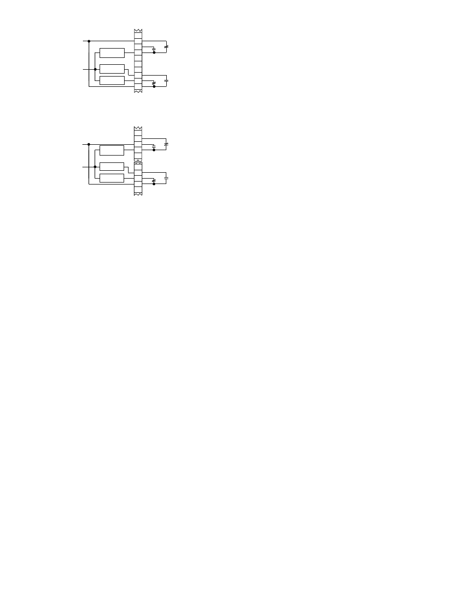
Figure 24—Normally Energized Load Circuit Connected to Alarm Relay
8
9
10
11
12
23
24
25
26
27
FIRE
RELAY
NO. 1
FAULT RELAY
FAULT RELAY SHOWN
IN NORMAL (ENERGIZED) CONDITION
A1058
FAULT
ALARM
LOAD
PROCESS
CONTROL
(
+
)H
(
–
)N
Figure 25—Normally Unenergized Load Circuit Connected to Fire Relay