Det-Tronics R7495D UV/IR Flame Detection System User Manual
Page 13
2. Remove the junction box cover assembly from the
base by loosening the six screws on the cover (see
Figure 12).
3.
Mount the detector junction box base and mounting
bracket assembly on the wall or ceiling. See
Figures 7 and 8 for dimensions of the mounting
bracket. The mounting surface should be free of
excessive heat and vibration.
NOTE
Do not wire the system, or plug in or remove the
sensor modules with power applied.
4. Figure 13 shows the detector terminal block. Letter
designations correspond to connections as indicat-
ed below.
A = +24 vdc
B = detector output signal
C = circuit ground
D = oi control signal
Minimum requirements for wiring the detector are for the
B-lead (signal) to be shielded. It is preferred that the A-
lead, C-lead, and D-lead also be shielded to provide
maximum immunity to EMI/RFI. The wiring procedure
below is the preferred method of detector to controller
wiring. Refer to Figure 14 for an example of detector to
controller wiring.
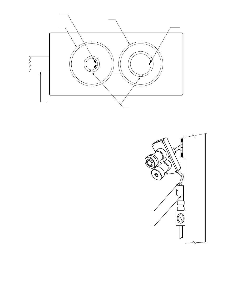
PROVIDE ENOUGH CABLE
FOR ADJUSTMENT OF SWIVEL
CONDUIT SEAL
A1478
Figure 11—Vertical Detector Mounting
13
95-8331
oi
RING OPENING DOWN
CONDUIT SEAL REQUIRED WITHIN 18 INCHES
OF DETECTOR. DETECTOR MUST BE ORIENTED
WITH CONDUIT ENTRY AT BOTTOM OR SIDE TO
ELIMINATE DRAINAGE INTO JUNCTION BOX.
*
oi
TEST LAMPS AT TOP OR SIDE
oi
TEST LAMP
*oi
TEST LAMP (2)
IR SENSOR HOUSING
UV SENSOR HOUSING
A1462
Figure 10—Front View of the C7052 Detector