Programming the controller – Det-Tronics R7495D UV/IR Flame Detection System User Manual
Page 18
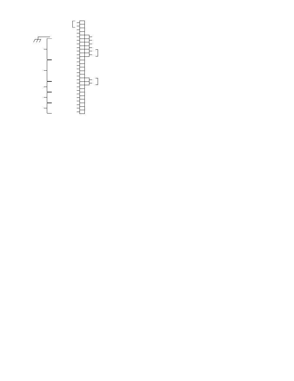
Terminal 4 —
Do not use.
Terminal 5 —
Chassis Ground
Terminals 6 to 11 —
Relay contacts - Fire Relay No.
1.
Terminals 12 to 17 —
Relay contacts - Fire Relay No.
2.
Terminals 18 to 20 —
Relay contacts - Alarm Relay
No. 1.
Terminals 21 to 23 —
Relay contacts - Alarm Relay
No. 2.
Terminals 24 to 26 —
Relay Contacts - Fault Relay.
Terminal 31 —
External Reset. To reset the
system from a remote location,
connect switch (normally open)
between terminals 31 and 32.
Terminals 32 and 33 — Circuit ground.
Terminal 34 —
Do not use.
Terminal 35 —
Connect to the D-lead (oi driv-
er) of Detector No. 1.
Terminal 36 —
Connect to the D-lead (oi driv-
er) of Detector No. 2.
Terminal 43 —
Connect to the B-lead (signal)
of Detector No. 1.
Terminal 44 —
Connect to the B-lead (signal)
of Detector No. 2.
PROGRAMMING THE CONTROLLER
The R7495D Controller is field programmable in order to
meet the requirements of the individual installation. This
is accomplished by setting rocker switches that are
located on the left side of the controller (see Figure 20)
to either “open” or “closed.” The programming options
are listed below. A more detailed description follows.
1. Number of detectors connected to the controller (1
or 2).
2. Gate Length, Consecutive Gate Selection, and
Count Selection (system sensitivity and time delay).
3. Fire zone grouping.
4. Latching/non-latching outputs.
The individual rocker switches are identified by num-
bers 1-1, 1-2, 1-3, etc. in this manual. The number pre-
ceding the dash indicates the number of the switch
assembly. The number following the dash identifies the
specific rocker on the switch assembly. See Figure 20.
The rockers are identified by the numbers one through
eight on one side of the assembly. The word “open”
can be seen on the opposite side. The switch is open
when depressed in the direction of the word “open” and
closed when depressed in the direction of the numbers.
The rocker switches must be set before power is applied
to the system. Do not plug the controller in or remove it
from the mounting rack while power is turned on.
CAUTION
Use care when setting the rocker switches on the
controller. An incorrectly set rocker switch can
result in an obvious controller malfunction, or the
controller could appear to be functioning normally,
but not produce the desired output in response to
the input conditions. (Some of the rocker switches
on the R7495D are not used. These rockers
should be left open.)
Detector Selection - Rocker Switches 1-1 and 1-2
The number after the dash corresponds to the channel
number. Open the rocker for each zone that has a
detector connected to it. Care must be taken when set-
ting these rockers. If a rocker is set open, but no detec-
tor is connected in that location, the controller will indi-
cate a fault. If a rocker is set closed when a detector is
connected, the controller will appear to be operating
correctly and will produce an alarm condition if the cor-
responding detectors sense a fire. However, that
detector will be eliminated from the Automatic oi test
sequence, and any faults occurring in its circuitry or
wiring will not be indicated.
18
J2
J1
1
2
3
4
5
6
7
8
9
10
11
12
13
14
15
16
17
18
19
20
21
22
23
24
25
26
31
32
33
34
35
36
43
44
+
–
NOT USED
NOT USED
CHASSIS GROUND
NORMALLY CLOSED
NORMALLY OPEN
COMMON
NORMALLY CLOSED
NORMALLY OPEN
COMMON
NORMALLY CLOSED
NORMALLY OPEN
COMMON
NORMALLY CLOSED
NORMALLY OPEN
COMMON
NORMALLY CLOSED
NORMALLY OPEN
COMMON
NORMALLY CLOSED
NORMALLY OPEN
COMMON
NORMALLY CLOSED
NORMALLY OPEN
COMMON
EXTERNAL RESET
CIRCUIT GROUND
CIRCUIT GROUND
NOT USED
D1
D2
B1
B2
FAULT*
RELAY
ALARM
RELAY
NO. 1
ALARM
RELAY
NO. 2
FIRE
RELAY
NO. 2
FIRE
RELAY
NO. 1
+
24 VDC INPUT
SIGNAL INPUTS
(B-LEADS)
oi
DRIVERS
(D-LEADS)
THE FAULT RELAY, SHOWN DE-ENERGIZED,
IS NORMALLY ENERGIZED IN THE NORMAL OPERATING MODE
WITH NO FAULTS OCCURING
*
B1055
Figure 19—Controller Terminal Configuration