Det-Tronics R7495D UV/IR Flame Detection System User Manual
Page 5
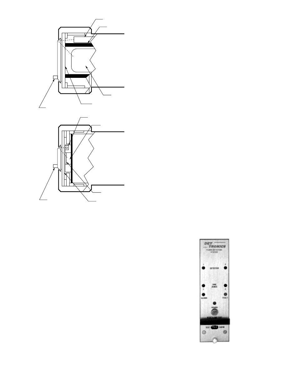
optical shield prevents the test beam from reaching the
sensor directly. The test beam travels out through the
viewing window, where it encounters the reflective oi
ring and is directed back through the window to the
sensor. Electronic circuitry in the detector then evalu-
ates the return signal from the sensor and generates the
appropriate output response. Since the test beam must
pass through the same portion of the viewing window as
radiation produced by a fire, this test of the ability of the
detector to “see” a flame has a high degree of reliability.
Enclosure
The C7052J features an explosion-proof, dust-tight, and
water-tight (NEMA 4/IP66) housing that is designed for
installation in hazardous locations in both indoor and
outdoor environments. The enclosure is FM approved,
CSA certified, and BASEEFA/ CENELEC approved.
CONTROLLER
The R7495D is designed for use with 24 volt dc power
supplies, but will operate from any direct current supply
between 18 and 32 volts. The unit will tolerate tran-
sients such as those that can occur when fully dis-
charged batteries are placed on charge. When power
is present at the R7495D Controller, it is indicated by a
continuously energized green LED. All other lights and
displays on the R7495D front panel are normally off, but
may be periodically checked for operation by pressing
the RESET/LAMP TEST button located directly below the
POWER light as illustrated in Figure 3.
With power applied and the TEST/NORM toggle switch
in the normal mode, the R7495D Controller continuously
cycles through the Automatic Optical Integrity test (see
the “oi Feature” section), checking each detector and
its wiring. At the same time, it monitors the system for
any status changes, such as a fault or a “fire” signal
from one of the detectors, or a change in the setting of
the TEST/NORM toggle switch. If a status change
occurs, the controller will respond accordingly by indi-
cating the change on the front panel and generating the
appropriate output.
Front Panel
The front panel of the R7495D provides a switch for
selecting mode of operation and initiating test functions.
It also provides LEDs for indicating system status.
Figure 3 illustrates the front panel of the controller.
1. A DETECTOR LED for each channel provides an
immediate visual indication that a fire has been
detected. The LED blinks slowly (once per second)
if the fire intensity does not exceed the fire thresh-
old and blinks rapidly if a fire output is generated.
Steady illumination indicates that the fire intensity
has returned below the alarm threshold (i.e., fire has
been extinguished).
UV DETECTOR
IR DETECTOR
UV TEST LAMP
OPTICAL SHIELD
VIEWING WINDOW
SNAP-IN
oi
RING
IR TEST LAMP (2)
IR SENSING ELEMENT
SNAP-IN
oi
RING
OPTICAL FILTER
VIEWING WINDOW
UV SENSOR
B1048
5
95-8331
Figure 2—
oi
Function within the Detector
Figure 3—Controller Front Panel
A1700