Controller installation and wiring – Det-Tronics R7495D UV/IR Flame Detection System User Manual
Page 17
17. If the detector is so equipped, install the air shields
on each sensor housing, then connect the air sup-
ply line to the air shields.
NOTE
Be sure that the detector is correctly aimed at the
potential hazard and that no obstructions interfere
with its line of vision. In addition, UV and/or IR
absorbing gases (see Table 2) should not exist
between the detector and the potential hazard.
CONTROLLER INSTALLATION AND
WIRING
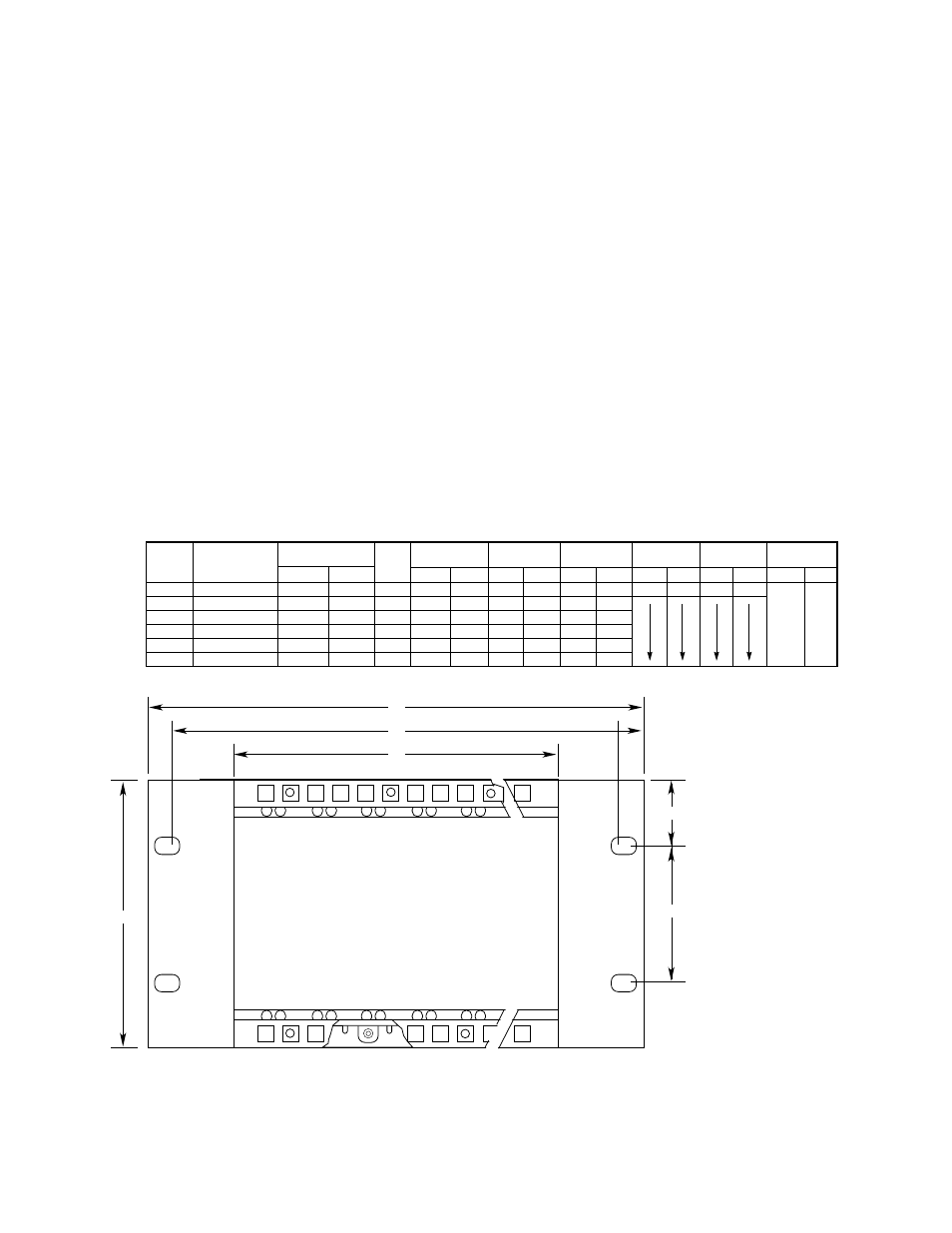
The R7495D Controller must be mounted in a non-haz-
ardous area. The optional Q4004 Mounting Cage is
designed to hold up to eight modules in a 19 inch
instrument rack. Other mounting cages are available to
accommodate 1, 2, 3, or 4 units. These mounting
cages can also house relay output modules, voltage
converters, or other micro-module equipment that is
used in conjunction with the R7495D Controller as part
of the total protection system. See Figure 18 for illustra-
tion and dimensions.
ELECTRICAL CONNECTIONS
All electrical connections are made to the field wiring
connector that is furnished with the controller. Figure 19
shows the terminal configuration for the controller.
Power to the R7495D Controller and C7052J Detectors
may be furnished by external 24 volt batteries, a regu-
lated dc power supply, or optional Det-Tronics voltage
converters. The R7495D is designed to operate on +18
to +32 vdc.
Terminal 1 —
Connect to the positive (+)
side of an external 24 vdc
power source (+18 to +32
vdc).
Terminal 2 —
Connect to the negative (–)
side of the dc power source
(circuit ground). The C termi-
nals on the detectors must also
be connected to circuit
ground.
Terminal 3 —
Do not use.
17
95-8331
(A)
(B)
(C)
1.48 (37.59)
(D)
A1475
ALL CONTROLLER CAGES REQUIRE
A MINIMUM OF 10.12 INCHES (257.1 MM)
DEPTH CLEARANCE
(E)
Figure 18—Q4004 Mounting Cage Dimensions in Inches (Millimeters)
RACK
PART NUMBER
CONTROLLER
TYPE
005269-XXX
POSITIONS FOR:
HT:
DIM. (A)
DIM. (B)
DIM. (C)
DIM. (D)
DIM. (E)
WEIGHT
FIRE GAS
INCH MM
INCH MM
INCH MM
INCH MM
INCH MM
LB
KG
4U
–001
8
16
4U
19.00
482.6
18.30
464.8
17.36
440.9
4.00
101.6
6.97
177.1
9.3
4.2
4U
–002
6
12
4U
15.06
382.6
14.36
364.7
13.42
340.9
7.6
3.5
4U
–003
4
8
4U
11.13
282.6
10.43
264.9
9.49
241.1
5.9
2.7
4U
–004
3
6
4U
9.16
232.7
8.46
214.9
7.52
191.0
5.1
2.3
4U
–005
2
4
4U
7.19
182.7
6.49
164.9
5.55
141.0
4.2
1.9
4U
–006
1
2
4U
5.22
132.6
4.52
114.8
3.58
90.9
3.1
1.4
3U
–007
16
3U
19.00
482.6
18.30
464.8
17.36
440.9
2.25
57.15
5.22
132.6
9.3
4.2
3U
–008
12
3U
15.06
382.6
14.36
364.7
13.42
340.9
7.6
3.5
3U
–008
8
3U
11.13
282.6
10.43
264.9
9.49
241.1
5.9
2.7
3U
–010
6
3U
9.16
232.7
8.46
214.9
7.52
191.0
5.1
2.3
3U
–011
4
3U
7.19
182.7
6.49
164.9
5.55
141.0
4.2
1.9
3U
–012
2
3U
5.22
132.6
4.52
114.8
3.58
90.9
3.1
1.4