Det-Tronics R7495D UV/IR Flame Detection System User Manual
Page 15
a. Connect the B-lead shields to the chassis
ground connection (terminal 5) of the con-
troller.
b. Be certain that the shield is NOT connected
to the detector at terminal “C” (circuit ground)
or any other points.
c. Connect the C-leads of the detectors to termi-
nal 2 (circuit ground) of the controller.
d. Connect a non-polarized 0.47 microfarad 250
vdc capacitor from terminal 5 to terminal 2.
This places the earth ground and the circuit
ground at the same ac potential, minimizing
induction of noise into the system through the
detector cable.
5.
Check to make sure that all wiring is correct. If con-
duit is used, pour the conduit seals and allow them
to dry.
6. If the UV and/or IR sensor modules are already
installed in the detector housing, proceed to step
12. If the sensors are not installed, remove the
applicable sensor housings from the junction box
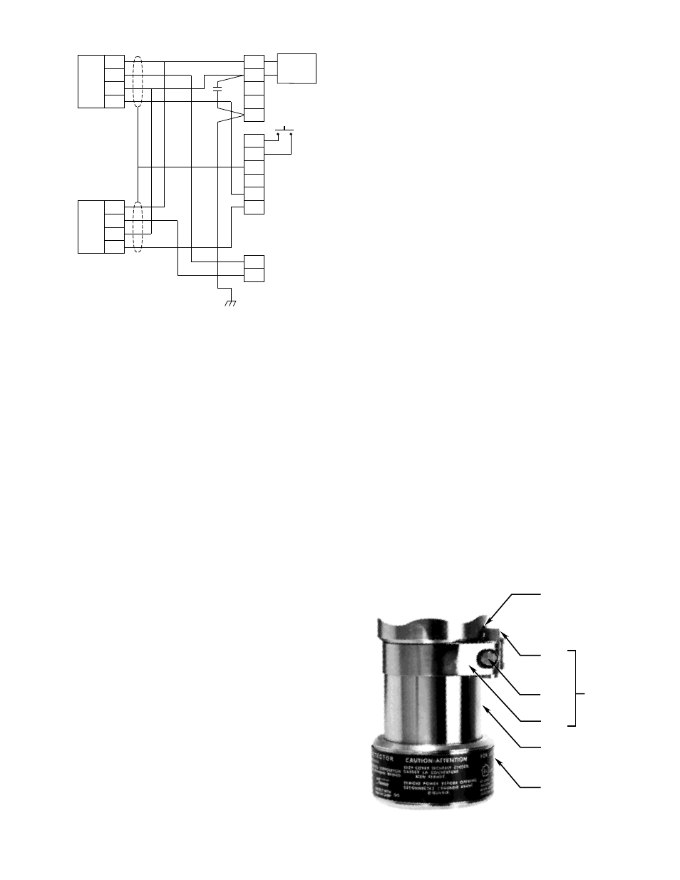
cover (see Figure 12). If the detectors are
equipped with a cover locking device (see Figure
15), loosen the clamp and disengage the “catch”
from the blind hole. The tool required is a 5/32-inch
hexagonal (Allen) wrench.
7.
If the UV sensor module is already installed, pro-
ceed to step 9. If the UV module is not installed,
remove the UV sensor module from its shipping
package.
8.
Determine the proper orientation for the UV module
by lining up the long index pin on the terminal block
with the hole in the printed circuit board of the mod-
ule. See Figure 12. Firmly press the module into
place on the terminal block, taking care not to touch
the glass envelope of the sensor module, since fin-
gerprints can absorb UV radiation and reduce the
sensitivity of the sensor.
IMPORTANT
If the UV sensor module is supplied with a jumper
plug “J” as shown in Figure 16, remove the jumper
plug from the detector tube module and discard it.
Jumper plug “J” is supplied for installations in
which the tube module is used with other detector
models.
NOTE
The C7052J contains semiconductor devices that
are susceptible to damage by electrostatic dis-
charge. An electrostatic charge can build up on
the skin and discharge when an object is touched.
Therefore, use caution when handling the detector,
taking care not to touch the terminals or electronic
components. For more information on proper han-
dling, refer to Service Memo form 75-1005 at the
front of this manual.
9.
If the IR sensor is already installed, proceed to step
12. If the IR sensor is not installed, remove the IR
module from its shipping package (avoid touching
the IR sensing element at the top of the module).
Two IR sensor designs exist: 1) the DE5500 is elec-
trically connected via a wire harness on the junction
box that must be threaded through the sensor mod-
ule to a connector at the top of the module (see
Figure 17), 2) the DE3895 plugs directly onto a termi-
nal block in the base of the IR housing via connec-
tors on the bottom of the IR sensor module (see
Figure 12).
15
95-8331
1
2
3
4
5
A
B
C
D
31
32
33
34
35
36
24 VDC
POWER
SUPPLY
–
+
43
44
DETECTOR
NO. 1
C7052J
A
B
C
D
DETECTOR
NO. 2
C7052J
J2
J1
REMOTE
RESET
CHASSIS (EARTH) GROUND
CHASSIS GROUND
D1
D2
B1
B2
CKT GND
0.47
µ
f
B1088
Figure 14—Detector Connection
BLIND HOLE
COVER
LOCKING
ASSEMBLY
CATCH
CLAMP
SCREW
STRAP
BARREL
LENS CAP
A1078
Figure 15—Cover Locking Assembly (Optional)