Serial interface – Dascom MIP480 User Guide User Manual
Page 118
Interface Information
D-2
Serial Interface
Use the cable that comes with the printer or equivalent. If you prepare a cable separately,
the cable connector at the printer side should be an equivalent that conforms to EIA stan-
dards.
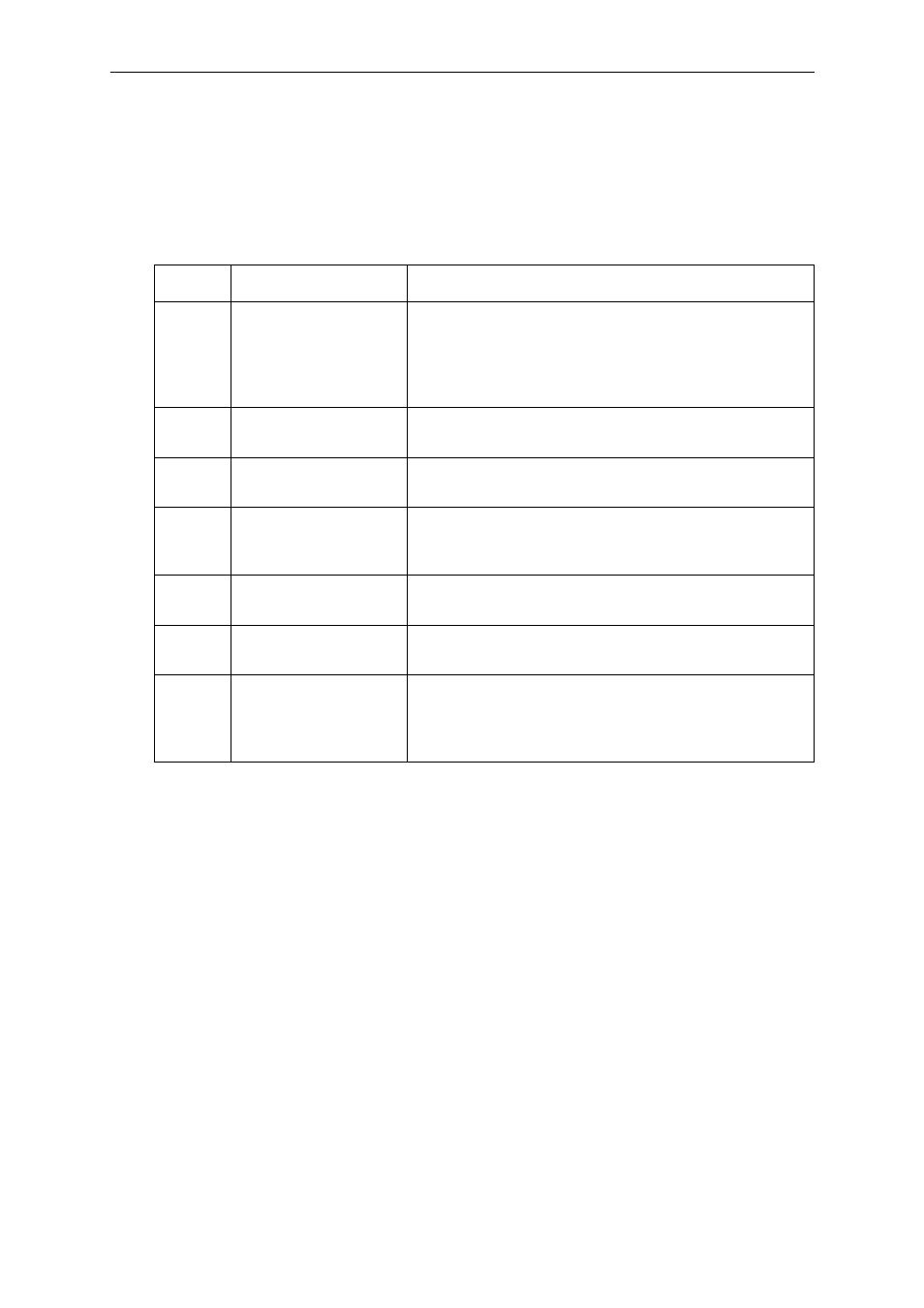
The following table shows the pin assignments that are used.
Pin No.
Signal Name
Description
2
TXD
(Transmit Data)
This line is for transmission of data from Printer to PC.
The characteristics of the data transmitted are specified
by the function menu. The only data that will be transmit-
ted are XON (x’11’) and XOFF (x’13’) signals. CTS must
be high for transmission to take place.
3
RXD
(Receive Data)
This line is for receiving data from PC. The serial inter-
face will not accept any data unless DSR is on.
4
RTS
(Request to Send)
This line will be set high and will remain high after the
serial interface finishes its Reset.
5
CTS
(Clear to Send)
This line will be monitored only if the XON/XOFF proto-
col is selected because CTS must be high in order for
the serial interface to transmit data.
6
DSR
(Data Set Ready)
DSR is used as another method of providing data integ-
rity. Data will not be accepted unless DSR is high.
7
SG
(Signal Ground)
Signal Ground (common return)
20
DTR
(Data Terminal Ready)
This line will be set high after the serial interface finishes
its Reset sequence. However if Ready/busy handshake
protocol is selected, this line is used to indicate to PC
whether or not Printer is ready to receive any more data.