Hardware description, 1 interface, 2 mode switch – Atop Technology GW51C-MAXI-WDT User manual User Manual
Page 10
User manual Version 1.4
GW51C-MAXI Serial Server
Copyright © 2004 Atop Technologies, Inc.
All rights reserved. Designed in Taiwan.
9 / 68
2. Hardware Description
2.1 Interface
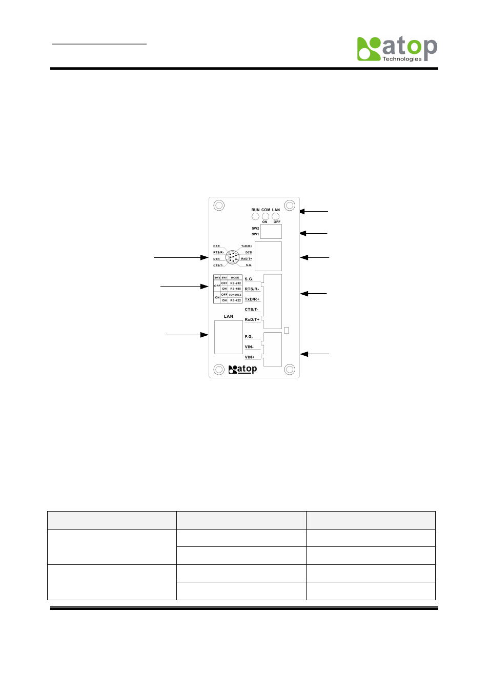
Figure 2.1 shows the interface of GW51C-MAXI Serial Server Connectors、LEDs & the factory switch
settings.
Mode Switch
Table
LED
Indicator
Mode Switch
Serial Port
Terminal Block
Connector
Power Supply Inpu
Connector
Mini-Din Pin
Assignment
UTP
Connector
Serial Port Mini D
Connector
Figure 2.1. Front Plate of
GW51C-MAXI Serial Server
2.2 MODE Switch
This sets or initializes the operating mode for the GW51C-MAXI Serial Server. The factory default setting
is that Switch 1 (SW1) and Switch 2 (SW2) are set to OFF. You can use the Mode switch to change the
operating mode from the factory default settings to your desired mode.
GW51C-MAXI Serial Server can be setup either RS-232, RS-485, RS-422 or Console configuration mode
by MODE Switch.
SW1
SW2
Mode
OFF RS-232
OFF
ON CONSOLE
OFF RS-485
ON
ON RS-422