Emr 2 engine side equipment -121 – JLG 1250AJP Service Manual User Manual
Page 169
SECTION 3 - 1CHASSIS & TURNTABLE
3121171
– JLG Lift –
3-121
The EMR2 is equipped with safety devices and measures
in the hardware and software in order to ensure emer-
gency running (Limp home) functions.
In order to switch the engine off, the EMR2 is switched in a
de-energized fashion over the ignition switch. A strong
spring in the actuator presses the control rod in the de-
energized condition into the zero position. As a redun-
dancy measure, an additional solenoid serves for switch-
ing off and this, independently of the actuator, also moves
the control rod in the de-energized condition into the zero
position.
After the programming, that is carried out over the
ISO9141 interface, the EMR2 is possesses a motor-spe-
cific data set and this is then fixedly assigned to the
engine. Included in this are the various application cases
as well as the customer’s wishes regarding a particular
scope of function.
Each EMR2 module is matched by serial number to the
engine. Modules cannot be swapped between engines.
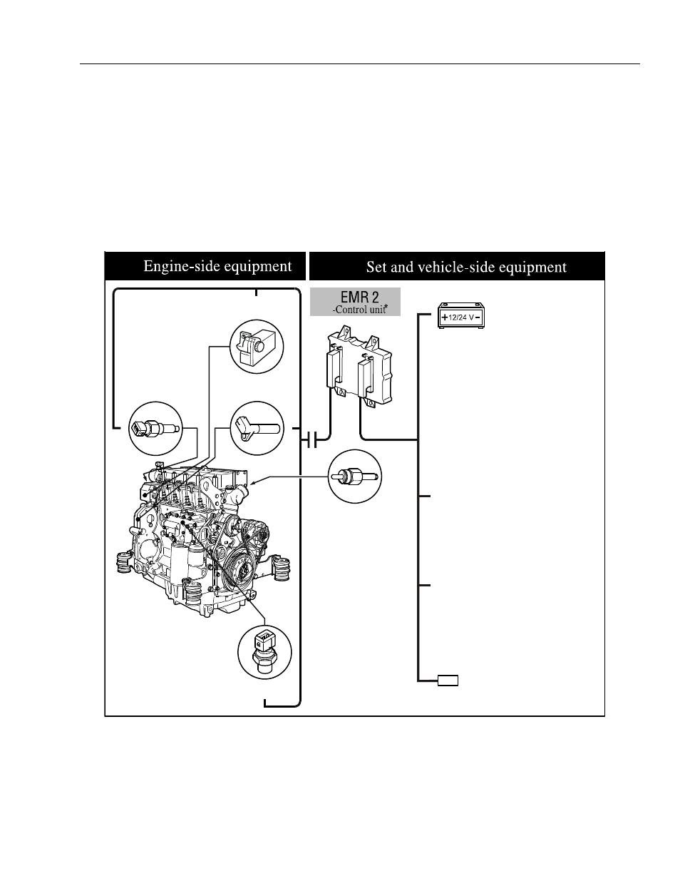
Figure 3-64. EMR 2 Engine Side Equipment
GLOW PLUG
POWER SUPPLY
COOLANT TEMPERATURE
SENSOR
CONTROL ROD POSITION
SENSOR/ACTUATOR
CAMSHAFT SPEED
SENSOR
OIL PRESSURE
SENSOR
JLG SYSTEM USES JLG ANALYZER TO
REPORT FAULTS
DIAGNOSIS INTERFACE/CAN-BUS; JLG SYS-
TEM USES THIS TO CONTROL THE ENGINE &
FAULT REPORTING.
JLG SYSTEM HANDLES ENGINE START/
STOP; EMR2 TAKES CONTROL OF THE
ENGINE AT 700RPM