1 push beam extend/retract cylinder removal, Push beam extend/retract cylinder removal, Caution – JLG G6-42A Service Manual User Manual
Page 54
Boom
3-16
G6-42A, G9-43A, G10-43A
3. Slowly pull the wire or rope guiding the extend chain
over the push beam, around the extend chain
sheave, under the push beam and stopping at the
extend chain/retract chain clevis.
4. Remove wire or rope secured to extend chain.
5. Place chain clevis rod to one side of push beam.
6. Lift the push beam to gain access to the chain clevis
at the rear of the third boom section.
7. Reaching inside rear of the boom at chain anchor
bracket, install cotter pin and pin from extend chain
clevis. Install cotter pin and pin from retract chain.
8. Lower the push beam. Center the chain clevis rod on
the push beam.
9. Place extend chain rod through strong back and
place strong back in place at the rear of the first
boom section.
10. Install and torque strong back mounting bolts to
240-265 lb-ft (325-359 Nm).
11. Install extend/retract cylinder mounting pin and
secure with retaining clips.
12. Install adjustment and lock nuts on chain clevis rod.
Do not tighten at this time.
13. Uncap and connect the extend/retract cylinder
hydraulic tubes to their appropriate locations.
14. Adjust the chain as needed. Refer to Section 3.8,
15. Install the cover on the rear of the boom.
16. Properly connect the battery.
17. Close and secure the engine cover.
18. Remove Do Not Operate Tags from both ignition key
switch and steering wheel.
3.7
PUSH BEAM—EXTEND/RETRACT
CYLINDER REMOVAL/
INSTALLATION
This section explains removal of push beam extend/
retract cylinder through front of boom assembly without
removing or disassembling boom assembly.
3.7.1
Push Beam Extend/Retract
Cylinder Removal
1. Park machine on a hard, level surface, level
machine, fully retract boom, level boom, place
transmission control lever in (N) NEUTRAL, engage
park brake and shut engine OFF.
2. Place a Do Not Operate Tag on both the ignition key
switch and the steering wheel.
3. Open engine cover. Allow system fluids to cool.
4. Remove cover from rear of first boom section.
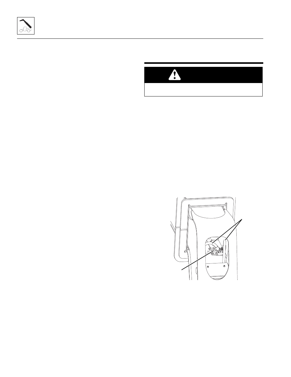
5. Disconnect both tilt hoses (1) and both auxiliary
hoses (not shown) from the hose retainer brackets
(2) at the bottom front inside the boom. Plug the
hose ends to prevent dirt and debris from entering
the hydraulic system.
6. Remove both hose retainer brackets (2).
CAUTION
The complete push beam - extend/retract cylinder
assembly weighs over 1,200 lb (545 kg).
MAL1310
1
2