4 engine coolant temperature sender, 5 fuel level sender, Engine coolant temperature sender – JLG G6-42A Service Manual User Manual
Page 178: Fuel level sender
Electrical System
9-22
G6-42A, G9-43A, G10-43A
9.10.4
Engine Coolant Temperature Sender
a.
Engine Coolant Temperature Sender Removal
1. Park machine on a firm, level surface, level machine,
fully retract boom, lower boom, place transmission
control lever in (N) NEUTRAL, engage park brake
and shut engine OFF.
2. Place a Do Not Operate Tag on both ignition key
switch and steering wheel.
3. Open engine cover. Allow system fluids to cool.
4. Properly disconnect the battery.
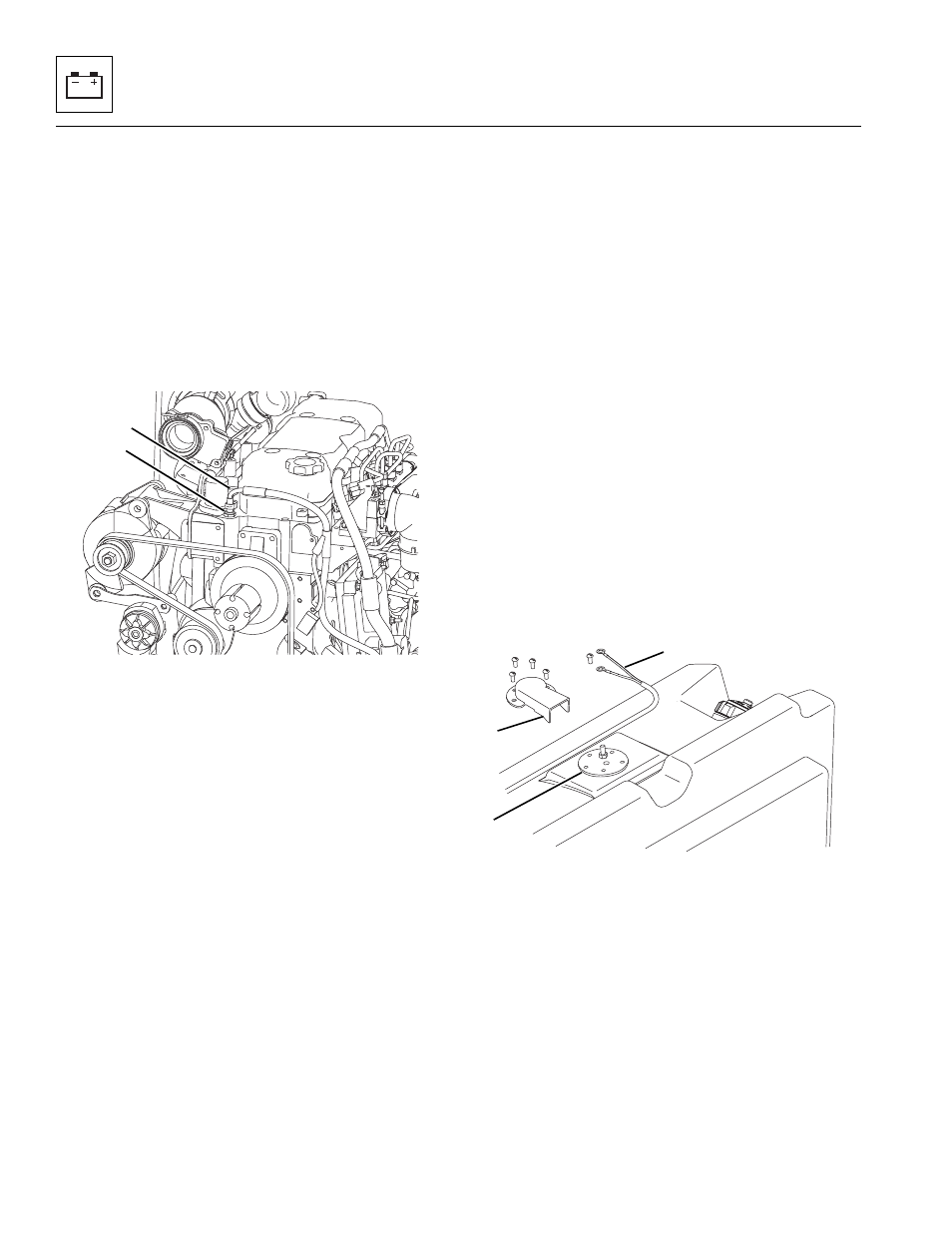
5. Unplug the engine coolant temperature sender
connector (1) from the wiring harness connector.
6. Engine coolant temperature sender (2) is located
near upper radiator hose thermostat housing and
threaded into engine block. Remove the sender.
b. Engine Coolant Temperature Sender Inspection
and Replacement
Inspect sender and wiring harness connector terminals
for continuity. Replace a defective or faulty sender with a
new part.
c. Engine Coolant Temperature Sender Installation
and Testing
1. Thread engine coolant temperature sender into
engine block snugly, then connect sender connector to
wiring harness connector.
2. Properly connect the battery.
3. Check for proper coolant level.
4. Start engine, allow it to reach operating temperature
and observe the operator’s instrument cluster for
warning indication. If sender is not defective, the
problem could be elsewhere; possibly in a shorted
wire, improper-running engine, improper or low
coolant, obstructed or faulty radiator, coolant pump,
loose fan belt, defective instrument display, etc.
5. Close and secure the engine cover.
6. Remove the Do Not Operate Tags from both the
ignition key switch and the steering wheel.
9.10.5
Fuel Level Sender
a. Fuel Level Indicator Testing
The fuel level sender wiring harness leads can be
accessed from the top of the fuel tank.
1. Loosen and remove he four screws securing the fuel
sender cover (6).
2. Disconnect the fuel level sender wiring harness
leads (7) from the fuel sender (8). With the help of an
assistant, touch both harness leads together.
3. From the operator’s cab, have the assistant turn the
ignition key switch to the RUN position. DO NOT
start the engine. Observe the fuel level indicator
needle on the operator’s instrument cluster. The
reading must be at the FULL mark.
4. Turn the ignition key switch to the OFF position. The
fuel level indicator needle should return to the
EMPTY position.
MY4620
2
1
MY4340
6
8
7