JLG G6-42A Service Manual User Manual
Page 57
3-19
G6-42A, G9-43A, G10-43A
Boom
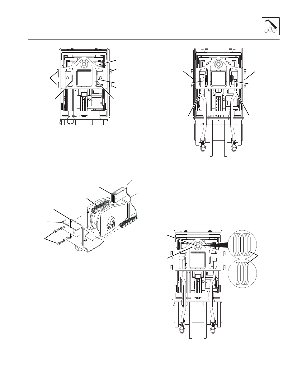
6. Install the strong back (1) with the previously
removed hardware (2) and torque as required.
7. Align the extend/retract cylinder bore with the strong
back bores and install the extend/retract cylinder pin
(3) and secure with the retaining clips (4).
8. Install anchor rod through front of boom assembly.
9. Connect the extend chain (5) to the anchor rod (6).
10. Install the guide bar (7) and chain retainer (8) to the
front of the push beam with the previously removed
hardware (9).
11. Properly connect the battery.
12. Start the machine and SLOWLY retract the extend/
retract cylinder until the push beam assembly bores
can be aligned with boom sections access bores.
13. Properly disconnect the battery.
14. Install both push beam pins (10) being careful to
align the pin mounting bolt holes.
Note: Disconnecting one or both extend/retract
hydraulic tubes (11) may be required to gain access to
the hose guide mounting bolts. After installing both hose
guides, re-connect one or both extend/retract hydraulic
tubes BEFORE preceding.
15. Install tilt cylinder hose guide (12) and auxiliary hose
guide from rear of third second section.
Note: Note position of belleville washers for reassembly.
MAL1290
4
1
3
4
2
2
2
MY3930
7
5
6
8
9
MAL1290
12
12
10
10
11
11
MAL2660
13
15
14
G6-42A
G9-43A
G10-43A