4 complete boom removal/ installation, 1 complete boom removal, 2 complete boom installation – JLG G6-42A Service Manual User Manual
Page 43: Complete boom removal/installation, Complete boom removal, Complete boom installation
3-5
G6-42A, G9-43A, G10-43A
Boom
3.4
COMPLETE BOOM REMOVAL/
INSTALLATION
3.4.1
Complete Boom Removal
1. Remove any attachment from quick switch assembly.
2. Remove the quick switch assembly. Refer to Section
3. Park machine on a hard, level surface, level
machine, fully retract boom, level boom, place
transmission control lever in (N) NEUTRAL,
engage park brake and shut engine OFF.
4. Place a Do Not Operate Tag on both the ignition key
switch and the steering wheel.
5. Open engine cover. Allow system fluids to cool.
6. Properly disconnect battery.
7. Using a suitable sling or hoist, support the boom.
8. Label, disconnect and cap the hydraulic hoses at the
rear of the boom. Cap all fittings to keep dirt and
debris from entering the hydraulic system.
9. Label and disconnect any electrical cables
(if equipped) at the rear of the boom.
10. Remove the pin from the rod end of the
compensation cylinder being careful not to drop the
cylinder. Lower the cylinder onto the frame rails.
11. Remove the pin from the rod end of the lift/lower
cylinder. Lower the cylinder onto the frame rails.
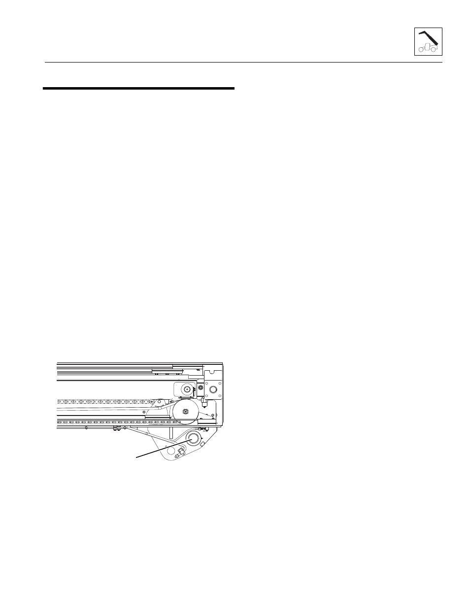
12. Confirm that boom assembly is balanced with sling
and remove the boom assembly pivot pin (1).
13. Lift boom assembly from machine and lower onto
suitable supports.
3.4.2
Complete Boom Installation
1. Using suitable slings, balance the boom assembly,
lift and carefully guide the boom into place. Align the
frame pivot bore with the boom assembly pivot bore.
Install the boom pivot pin (1).
2. With the sling still in place, install the compensation
cylinder, pins and bolts. Apply Loctite
®
242
TM
and
torque lock bolt to 100-110 lb-ft (135-149 Nm).
3. With the sling still in place, install the rod end of the
lift/lower cylinder, pin and lock bolt. Apply Loctite
®
242
TM
and torque lock bolt to 200-215 lb-ft
(271-291 Nm).
Note: Raising boom up or down with sling my be
necessary so boom, compensation and lift/lower cylinder
bores can be aligned for easier pin installation.
Note: Grease the boom pivot bore, compensation
cylinder rod end, lift/lower cylinder rod end and pins
before installing.
4. Uncap and reconnect the previously labeled
hydraulic hoses to the extend/retract cylinder.
5. Uncap and connect and remaining hydraulic fittings
to their appropriate locations.
6. Recheck wear pad gaps to ensure they meet the
minimum gap requirement. Shim if necessary.
7. Ensure that the boom chains are properly adjusted.
Refer to Section 3.8, “Boom Adjustments.”
8. Properly connect the battery.
9. Install the quick switch assembly. Refer to Section
10. Start engine and operate all boom functions several
times. Check for leaks, and check hydraulic fluid
level in reservoir; add fluid if required.
11. Clean up all debris, hydraulic fluid, etc., in, on, near
and around the machine.
12. Close and secure the engine cover.
13. Remove Do Not Operate Tags from both ignition key
switch and the steering wheel.
14. Install the previously removed attachment to the
quick switch assembly.
MY1520
1