JLG G6-42A Service Manual User Manual
Page 85
4-9
G6-42A, G9-43A, G10-43A
Cab and Covers
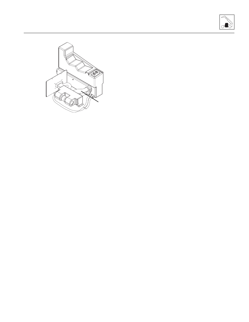
13. Loosen the hose clamps, label and disconnect the
heater hoses (16). Cap or plug the hoses to prevent
debris from entering the heater system.
14. Label and disconnect any electrical connections.
15. Remove the bolts securing the heater assembly to
the cab. Remove the heater assembly.
b. Heater Assembly Installation
1. Position the heater assembly to its original orientation
in the cab. Secure with the previous hardware.
2. Connect the previously labeled electrical
connections.
3. Connect the previously labeled heater hoses to their
appropriate locations.
4. Install the seat riser weldment.
5. Install the front plate to the seat riser weldment.
6. Install the cab seat.
7. Fill the cooling system completely, allowing time for
the coolant to fill the engine block. The cooling
system fluid and capacity is listed in Section 2.5,
“Fluid and Lubricant Capacities.”
8. Reinstall surge tank cap.
9. Properly connect the battery.
Note: When the engine is initially started, run it briefly at
low idle and check the machine for any visual sign of
fluid leakage. STOP the engine immediately if any
leakage is noted, and make any necessary repairs
before continuing.
10. Wait for engine to cool and check the coolant level.
Add coolant as required to bring the coolant to the
proper level.
11. Close and secure the engine cover.
12. Remove the Do Not Operate Tags from both the
ignition key switch and the steering wheel.
MY0200
16