5 cab installation, Cab installation – JLG G6-42A Service Manual User Manual
Page 87
4-11
G6-42A, G9-43A, G10-43A
Cab and Covers
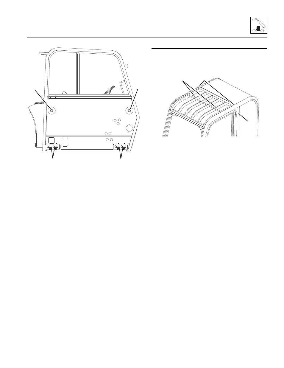
20. Remove two cab side-mount bolts in cab (17).
21. Remove the four cab-to-frame bolts, flat washers and
nuts (18).
22. Remove the mirrors and all other cab components
as needed, if not previously removed.
23. Carefully begin to lift the cab. Stop and check that all
wiring, hydraulic hoses and fasteners are
disconnected or removed.
24. When all wiring, hydraulic hoses and fasteners are
disconnected or removed, carefully and slowly lift the
cab and remove it from the frame. Readjust the
position of the sling as needed to help balance the
cab during removal.
25. When cab is completely clear of machine, carefully
lower it to ground. Block up or support the cab so
that it does not move or fall. Assure that no
personnel enter cab while it is being removed from
the machine.
26. Inspect condition of fittings, clamps, hydraulic hoses,
etc. Replace parts as indicated by their condition.
27. Inspect and replace machine parts that are exposed
with cab removed. Repair or replace as required.
4.5
CAB INSTALLATION
1. Block all four wheels to help prevent the machine
from moving. Assure that there is sufficient overhead
and side clearance for cab installation.
2. Open Cab: Route a sling with a minimum lifting
capacity of 1000 lbs (453 kg) under the inner four
braces (14) and behind the center cross support
above the wind shield or install two lifting eye bolts
(15) in the threaded holes on the roof of the cab
above the B pillars (16).
3. Enclosed Cab: Install two lifting eye bolts (14) in
threaded holes on roof of cab above B pillars (16).
4. Use a hoist or overhead crane and sling attached to
the cab. Carefully begin to align the cab with the
mounting holes in the frame. Stop and check that
wiring, hydraulic hoses, cables, etc., will not be
pinched or damaged as the cab is positioned.
5. Readjust position of sling as needed to help balance
cab during installation.
MY4170
18
17
17
18
MY0610
14
15
16