9 quick switch assembly, 1 hydraulic quick switch removal, Quick switch assembly – JLG G6-42A Service Manual User Manual
Page 63: Hydraulic quick switch removal, Refer to section, 9, “quick switch assembly
3-25
G6-42A, G9-43A, G10-43A
Boom
13. Start the machine and at low idle, fully extend and
retract the boom three times. Verify boom is fully
retracted and level. Shut machine Off.
14. Verify dimension “A” 17.000-17.312 in
(421,8-439,7 mm). Verify dimension “C” is not
less than 3.069 in (77,9 mm).
Note: Re-adjust boom if dimensions “A” & “C” are not
met. Contact the local JLG Distributor if the procedure
cannot be obtained.
15. Loosen the retract chain lock nut and the extend
chain lock nut and apply Loctite
®
242
TM
.
16. Torque the retract chain lock nut (5) and extend
chain lock nut (1) without adding any additional
spring load. Torque each lock nut to 100 lb-ft
(135 Nm).
3.9
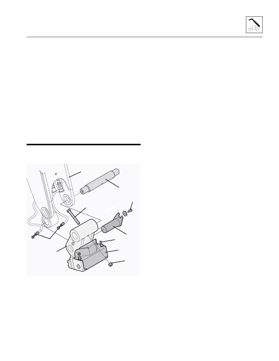
QUICK SWITCH ASSEMBLY
3.9.1
Hydraulic Quick Switch Removal
1. Remove hardware securing cylinder cover (15) and
remove cylinder cover.
2. Remove clamp hardware (16) securing cylinder
cover to hydraulic hoses (17).
3. Label and disconnect hydraulic hoses (17) attached
to quick switch assembly (10). Drain fluid into
suitable container.
4. Plug and cap the hose ends to prevent dirt and
debris from entering the hydraulic system.
5. Remove lock bolt (8) holding tilt cylinder rod end pin
(9) to quick switch assembly (10). Remove tilt
cylinder rod end pin.
6. Support quick switch assembly (10). Remove
capscrew (11) and locknut (12) securing head pin
(13) to boom head (14).
7. Remove the head pin (13) and the quick switch
assembly (10)
8. Inspect above pins for nicks or surface corrosion.
Use fine emery cloth to fix minor nicks or corrosion.
If damaged or if it cannot be repaired pin must
be replaced.Hydraulic Quick Switch Installation
1. Assemble quick switch assembly (10) to boom head
(14). Line up quick switch between mounts on boom
head. The quick switch should be centered in the
boom head.
2. Coat head pin (13) with an anti-seize compound.
Insert head pin through quick switch and boom
head. Secure with capscrew (11) and locknut (12).
3. Align quick switch with tilt cylinder rod end and insert
tilt cylinder rod end pin (9). Align tilt cylinder rod end
pin and screw in locking bolt (8). Torque as required.
4. Uncap and install hydraulic hoses (17) to proper
fittings on quick switch assembly (10). torque
as required.
5. Secure hoses (17) to cylinder cover (15) with clamp
hardware (16).
6. Reinstall cylinder cover (15) with the hardware
removed earlier.
MY7390
13
12
10
11
8
9
14
15
16
17