Notice – JLG G6-42A Service Manual User Manual
Page 48
Boom
3-10
G6-42A, G9-43A, G10-43A
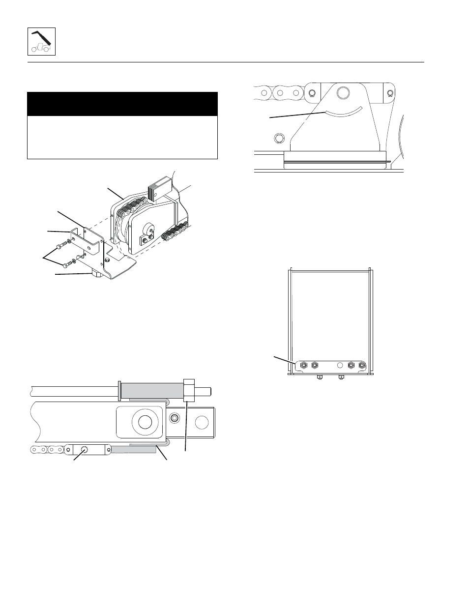
4. Relocate the sling and slowly insert the push beam
assembly into the front of the third boom section.
5. Install the push beam wear pad (4) to the previously
removed chain retainer (5) using two bolts and two
washers. Torque as required.
6. Lift the push beam assembly (6) with pry bars using
the access holes on each side of the third boom
section and install the guide bar (7) and chain
retainer (5) using the previously removed hardware
(8). Torque to 25-30 lb-ft (34-41 Nm).
7. Loosen the Temporary Extend Chain Bracket (9).
8. Apply thread lubricant to clevis mounting pin (10).
9. Lift push beam and install pin and retaining clips (10)
securing clevis to third boom section.
10. Remove the Temporary Retract Chain Bracket (11).
11. Install tilt cylinder hoses and (if equipped) auxiliary
hoses through front of third boom section.
Note: Verify tilt cylinder hoses and (if equipped)
auxiliary hoses are routed UNDER hose guide (12) at
rear of third boom section at retract chain clevis bracket.
12. Snug the Temporary Extend Chain Bracket (9).
13. Install the hose retainer assembly (13) using existing
hardware. Torque as required.
14. Remove caps from the hose retainer fittings and
plugs from the tilt cylinder hoses and (if equipped)
the auxiliary hoses.
15. Connect tilt cylinder hoses and (if equipped) the
auxiliary hoses to their proper locations. Torque
as required.
NOTICE
Guide the push beam/extend/retract cylinder
assembly over the top of the retract chain anchor at
the rear of the third boom section being careful not to
damage any components.
MY3930
7
6
4
5
8
MY4060
9
10
11
MY3940
12
MY3900
13