5 boom section removal/installation, 1 second and third boom section removal, Boom section removal/installation – JLG G6-42A Service Manual User Manual
Page 44: Second and third boom section removal
Boom
3-6
G6-42A, G9-43A, G10-43A
3.5
BOOM SECTION
REMOVAL/INSTALLATION
3.5.1
Second and Third Boom
Section Removal
Note: Refer to Section 3.13.2, 3.15. “Push Beam
Temporary Brackets,” for diagrams of the Temporary
Extend Bracket and Temporary Retract Bracket
designed to hold the chains in place on the push beam
during disassembly and reassembly.
These brackets are NOT a purchasable part and must be
manufactured locally.
They are solely designed to aid in the removal and
installation of the push beam assembly.
Note: Refer to Section 8.8, “Hydraulic Cylinders.” for
general tilt cylinder removal.
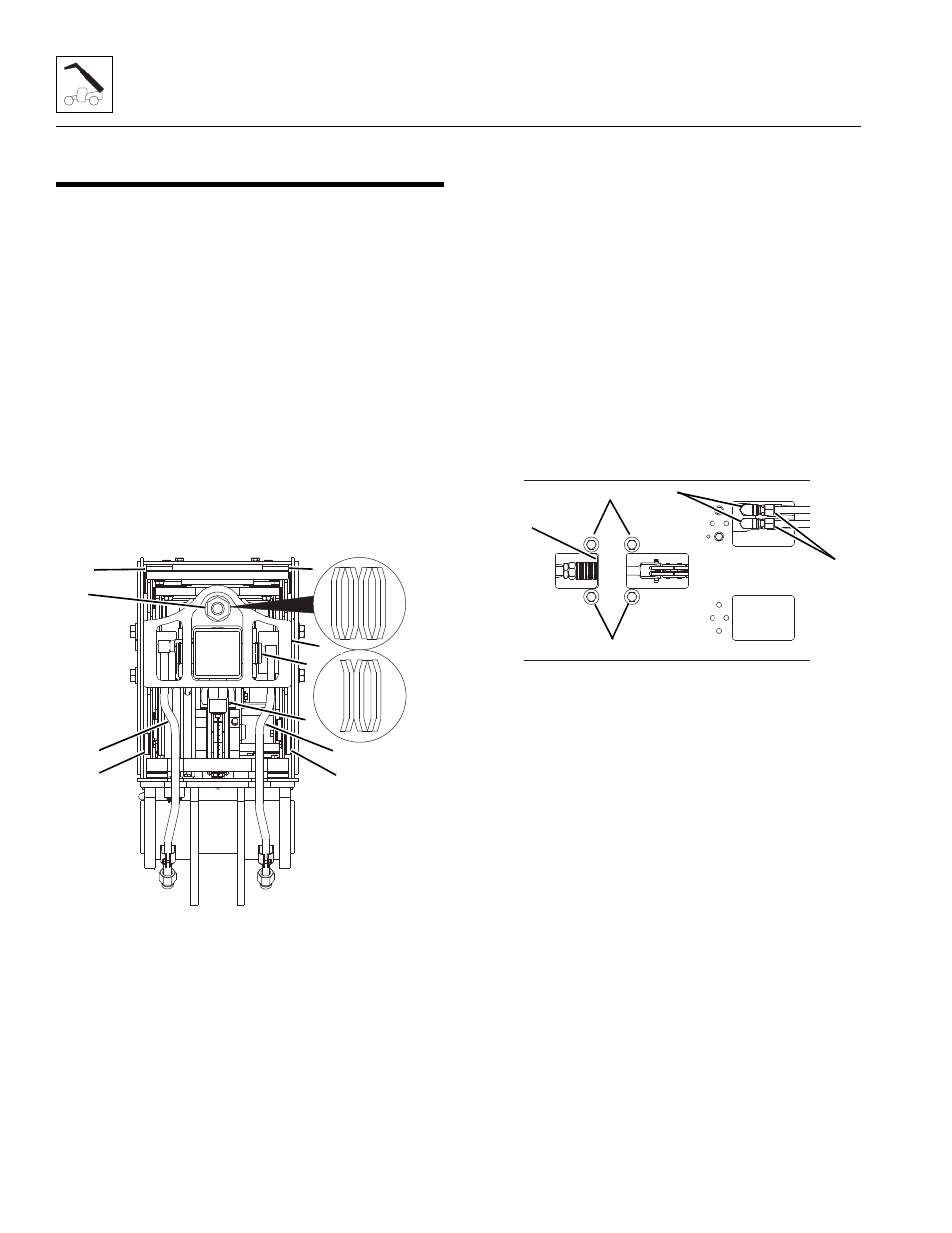
1. Remove the access cover from the rear of the first
boom section.
2. Remove the locknut, adjustment nut and six
belleville washers (1) from the extend chain clevis
rod at the rear of the boom.
3. Loosen and remove both extend/retract cylinder
tubes (2) from rear of boom. Cap and/or plug all
open hoses, tubes and/or fittings to prevent dirt and
debris from entering the hydraulic system.
4. Slowly loosen and remove the extend/retract
cylinder counterbalance valve (3). Plug (M27x1.5)
open port on extend/retract cylinder to prevent dirt
and debris from entering hydraulic system.
5. Remove retaining clips from extend/retract cylinder
mounting pin (4), remove extend/retract cylinder pin.
6. Remove four mounting bolts securing the strong
back (5) to the first boom section.
7. Remove strong back (5) from rear of boom.
8. Remove right or left side wear pads, shims and
backing plates (6) from rear of second boom section.
Label and tag each set of wear pads being removed.
9. Remove the top wear pads, shims and backing
plates (7) from the rear of the second boom section.
Label and tag each set of wear pads being removed.
10. Loosen and remove the four bolts (8) securing the
retract chain anchor plate (9).
11. Between bottom front of first and second boom
sections, feed a rope or wire to retract chain anchor
plate and secure to second or third boom section.
12. Disconnect both tilt tubes (10) and (if equipped) both
auxiliary tubes from fittings on hose retainer brackets
(11) at bottom front inside the boom. Plug the tube
ends to prevent dirt and debris from entering the
hydraulic system.
13. Disconnect both tilt hoses (not shown) and (if
equipped) both auxiliary hoses from hose retainer
brackets at bottom front inside the boom. Plug hose
ends to prevent dirt and debris from entering the
hydraulic system.
14. Loosen and remove the hose retainer brackets (11)
and (if equipped) both auxiliary take-up brackets.
MAL2660
1
2
2
4
5
6
3
6
7
7
G6-42A
G9-43A
G10-43A
MY3860
10
11
9
8
8