4 installation, Installation – Eppendorf PatchMan NP 2 User Manual
Page 24
69
Note: The connections between the control board, the mains power supply unit and the motor
module must only be plugged and unplugged with the device switched off.
Note: Do not place the control board down resting on the joystick! When connecting cables,
place the control board on its side on an even surface and secure it against toppling over!
–
The connection to the motor module is made via the corresponding connectors, as shown
in Figure 4.
–
Check the voltage and frequency against the rating plate before connecting the mains
power!
–
Use only the mains power supply unit supplied by Eppendorf!
–
The cable is plugged into the mains power supply unit before being connected to the mains.
Important:
The main power connection is the last one to be connected.
–
Check that the connectors are firmly attached.
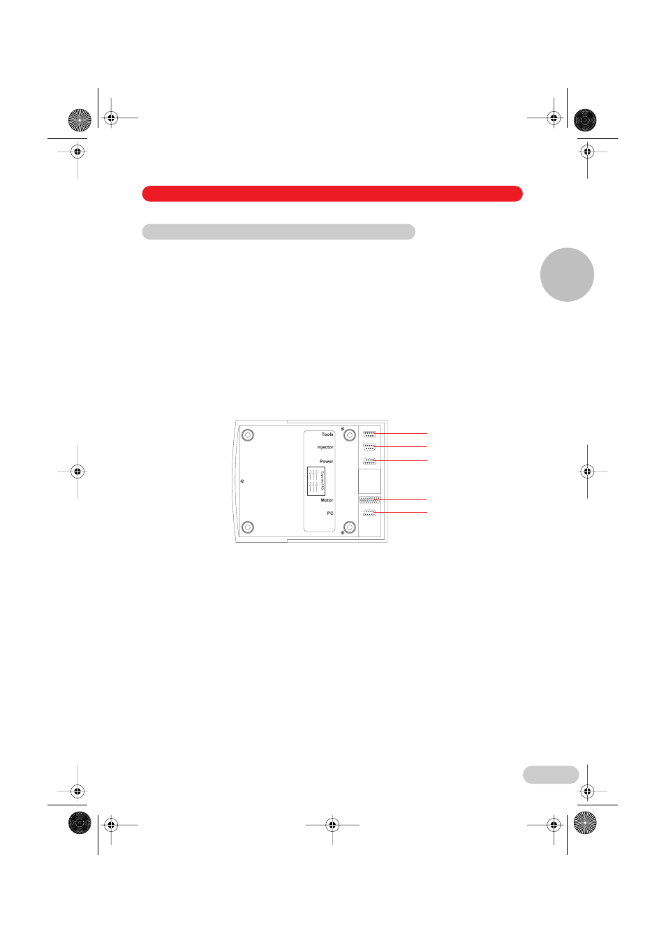
Fig. 4: Underside of control board
1 Connection for optional foot switch (position change) (SER2; SubD9, male)
2 Connection (SER1; SubD9, male) (not used on the PatchMan
NP 2)
3 Mains power supply connection
(Important:
Connect only when all the other components have been connected.)
4 Connection for motor module (SubD25, female)
5 Serial port (SER0; SubD9, male) for computer (RS 232)
4.4 Connecting cables – Startup
1
2
3
4
5
4 Installation
Installation
4
04_Install_e.fm Seite 69 Dienstag, 16. August 2005 3:17 15