3 description, Description – Eppendorf PatchMan NP 2 User Manual
Page 10
55
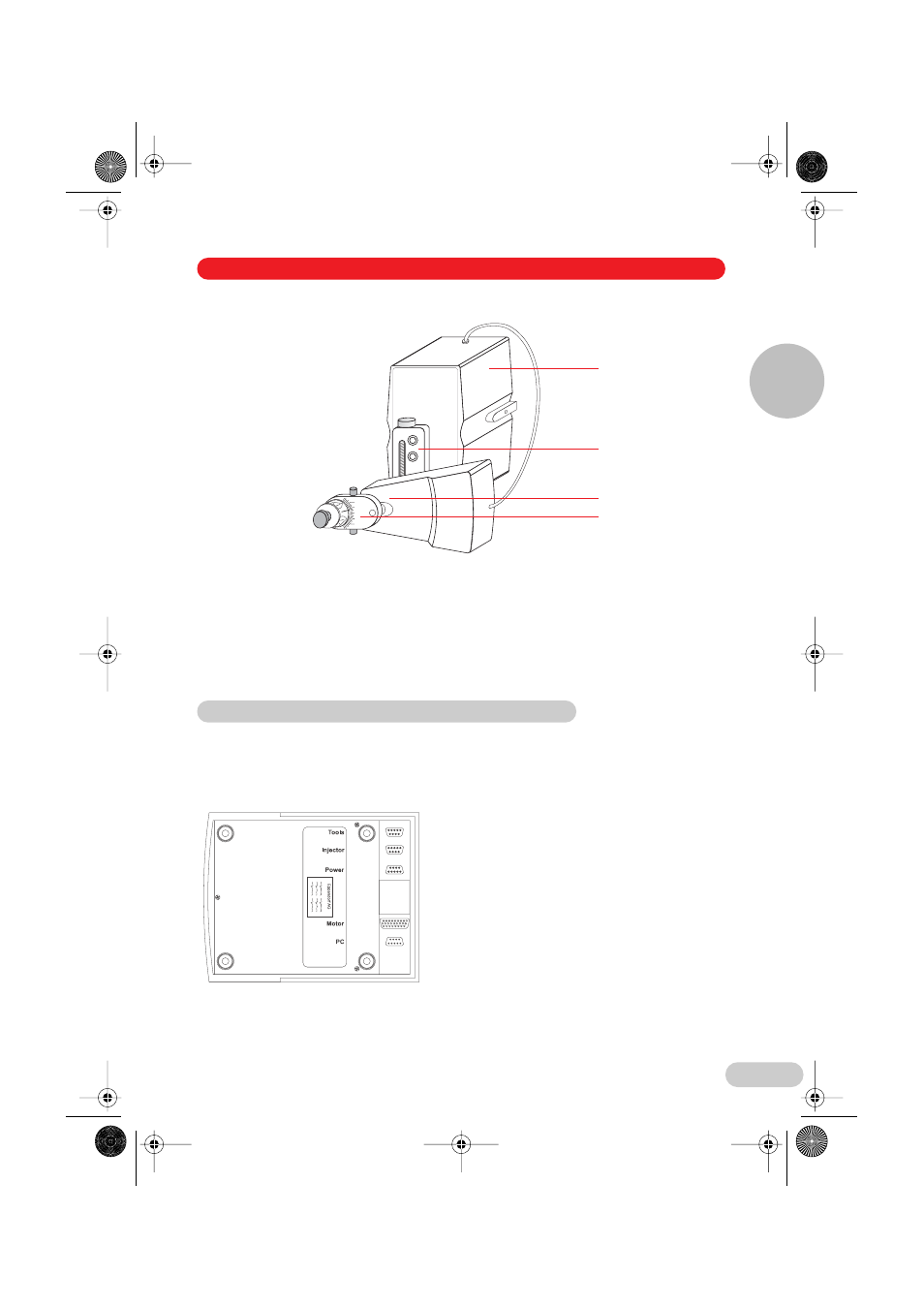
Fig. 2: Module unit (here right side mounted)
1 Motor unit for Y and Z axis movement (Y/Z module)
2 X module straight-line guide
3 Motor unit for X axis movement (X module)
4 X head with angle adjustment
The control board accommodates the keypad and the joystick with integral button, as well as
the turn wheel on the side. The movements performed on the joystick are transmitted to the
module unit. The movement modes, directions and speeds, as well as movement sequences,
are pre-set and triggered by way of the keypad, the turn wheel and the joystick.
Underside
The bay underneath the control board
accommodates the connector sockets for
the module unit and the mains power supply
as well as the serial port and the connection
for an optional foot switch.
Note: Do not place the control board down
resting on the joystick! When connecting
cables (section 4.4), place the control board
on its side on an even surface and secure it
against toppling over!
0
40°
40°
20°
20°
1
2
3
4
3.3 Control board
3 Description
Description
3
03_Geraet_e.fm Seite 55 Dienstag, 16. August 2005 3:15 15