4 installation, Installation – Eppendorf PatchMan NP 2 User Manual
Page 14
59
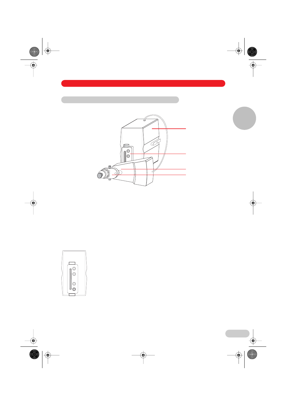
4.2.1 Components of the module unit
Fig. 3: Module unit (here right side mounted)
1 Motor unit for Y and Z axis movement (Y/Z module)
2 X module straight-line guide
3 Motor unit for X axis movement (X module)
4 X head with angle adjustment
4.2.2 Straight-line guide
The X module is assembled by bolting the straight-line guide onto the Y/Z module.
The height of the X module can be adjusted to the mounting point of the straight-line guide.
For the sake of clarity, the X module is not shown.
Example:
The straight-line guide is bolted to the Y/Z module through the bottom
hole. The X module can be height adjusted by turning the spindle.
4.2 Assembling the module unit
0
40°
40°
20°
20°
1
2
3
4
4 Installation
Installation
4
04_Install_e.fm Seite 59 Dienstag, 16. August 2005 3:17 15
- epMotion 96 (76 pages)
- epMotion 5070 (100 pages)
- epMotion 5075 (130 pages)
- Centrifuge 5427 R (64 pages)
- Centrifuge 5427 R (104 pages)
- White Paper 14 (8 pages)
- Rolling Cabinet (34 pages)
- Mastercycler nexus (118 pages)
- Mastercycler nexus (142 pages)
- Concentrator plus (New Design) (48 pages)
- Concentrator plus (43 pages)
- Easypet 3 (38 pages)
- Xplorer (74 pages)
- Xplorer Adjustment (26 pages)
- AF2200 Plate Reader (72 pages)
- AF2200 Plate Reader (78 pages)
- G0.5 µPlate (32 pages)
- BioSpectrometer basic (104 pages)
- BioSpectrometer kinetic (106 pages)
- BioSpectrometer fluorescence (102 pages)
- Micro Test Tubes (5 pages)
- Microplates (10 pages)
- PiezoXpert (34 pages)
- Eporator (38 pages)
- MiniSpin (20 pages)
- MiniSpin (25 pages)
- 5702 Centrifuge (32 pages)
- Centrifuge 5702 (32 pages)
- 5702 Centrifuge (27 pages)
- C5702 RH Centrifuge (32 pages)
- 5418 Centrifuge (80 pages)
- 5418 Centrifuge (48 pages)
- 5424 Centrifuge (71 pages)
- 5424 Centrifuge (44 pages)
- 5430 Centrifuge (130 pages)
- 5430 Centrifuge (88 pages)
- 5804 Centrifuge (129 pages)
- 5804 Centrifuge (95 pages)
- 5804 Centrifuge (127 pages)
- TransferMan4 r (102 pages)
- TransferMan4 m (96 pages)
- InjectMan 4 (100 pages)
- InjectMan NI 2 (60 pages)
- InjectMan NI 2 (16 pages)