Aerovent IM-500 User Manual
Page 9
9
Aerovent IM-500
Flame Safeguard Control
(Aerovent Part #25941-01)
All units are equipped with a Honeywell RM7895C flame
safety relay. This relay senses if a pilot flame and main
burner flame have been established through the use of an
ultraviolet (UV) scanner. For more information about the
Honeywell flame relay, visit the Honeywell web site.
The flame safeguard relay has a built in component self
checking module, pre-purge timer, and an ignition timing
flame sensing circuit. The pre-purge timer allows purg-
ing of any residual gas or fumes in the unit before a try
for ignition. Pre-purge is approximately 10 seconds. After
pre-purge occurs, the spark ignition will start. If the pilot
flame is not proven within the time period allowed (10 to
25 seconds) the relay will go into lockout and it will have
to be manually reset before a try for re-ignition can occur.
This can be accomplished by pressing the reset button on
the remote station or at the unit thus preventing a trip to
the air make-up unit. If after several (2-3) tries the unit
won’t light off, have a maintenance man inspect the unit to
determine cause of relay lockout.
Note: The power light
will blink; this is a normal operating condition.
C7027 Ultra Violet Scanners
(Aerovent Part #2281-01E)
Units are equipped with a C7027A UV scanner. This device
is shipped removed from the flame sighting tube to prevent
damage during shipment. Unwrap the device and mount
on the sighting tube. The UV scanner is a ultra-violet light
sensing device. It takes advantage of the fact that a flame
will emit some of its light in the low frequency ultra violet
light range. The scanner uses an electronic eye to scan for
the presence of this ultra violet light. If flame is detected,
it sends this signal to the RM7895C flame relay.
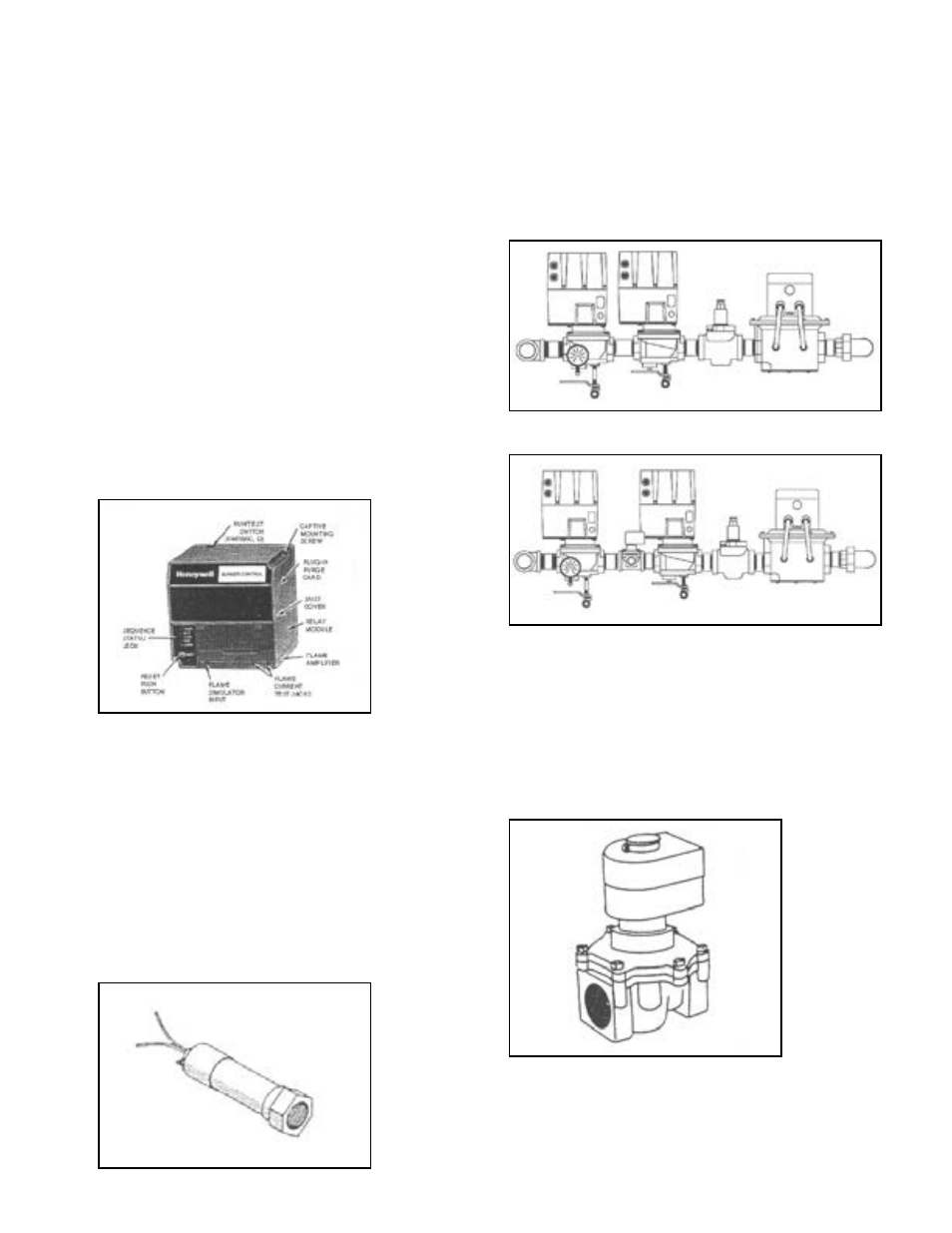
Gas Pipe Train Configuration
(Aerovent Part #2281-01E)
The type of manifold supplied with the unit varies depend-
ing on whether the unit was ordered with a FM or IRI
manifold. To determine which arrangement was supplied
with the unit, see the manifold descriptions noted on the
product specification and general description page in the
front of this manual.
Pilot Solenoid Gas Valve
(Aerovent Part #422-05E)
The pilot solenoid gas valve serves as a separate shut-off
valve for the pilot gas during normal operation and pro-
vides means for interrupted pilot and main flame supervi-
sion during normal operation of the unit.
Figure 7. FM Piping
Figure 8. IRI Piping
Figure 9. Pilot Valve
Figure 5. Flame Relay
Figure 6. UV Flame Detector (Purple Peeper)