Aerovent IM-500 User Manual
Page 11
11
Aerovent IM-500
flame MUST be a “clean blue flame”. A little yellow
tipping is acceptable, but the flame should be blue. The
flame length should be a maximum of 10-12 in.
3. Reconnect the wires to terminals #4.
Low Fire or By-Pass Adjustment
1. Disconnect wire from terminal #8 on the A1044 or
A1014 Amplifier. This causes valve to call for continu-
ous low fire.
2. Remove cap (B), Figure 12, and loosen lock screw (C).
Turn (D) to desired low fire adjustment. (Clockwise
rotation reduces minimum flow rate.) Flame should be
stable over full length of burner.
3. Tighten set screw (C), replace cap (B) and reconnect
wire to terminal #8.
NOTE: This procedure is in the Maxitrol bulletin found at
www.maxitrol.com. Please consult it for further information.
Blocking Main Gas and Vent Valve Systems for
FM and/or IRI Insurance Requirements
To meet the national insurance requirements of FM
(Factory Mutual) or IRI (Industrial Risk Insurers) these
controls are furnished in addition to the gas controls
required by ANSI.
Motorized Main Gas Valve(s)
FM and IRI (and some local codes) require the use of one
or two motorized main gas shut off valves and depends on
the BTU input capacity of the burner.
The motorized gas valve contains a heavy duty spring
which will return the valve to the closed position if power
is interrupted to the valve. The valve uses a hydraulic pump
to open the valve. The use of self closing heavy duty return
springs provides a positive shut off in the event of a power
loss to the valve. A second blocking valve prevents gas
escaping into any occupied space should the main gas valve
not provide tight shut-off when the unit is shut down.
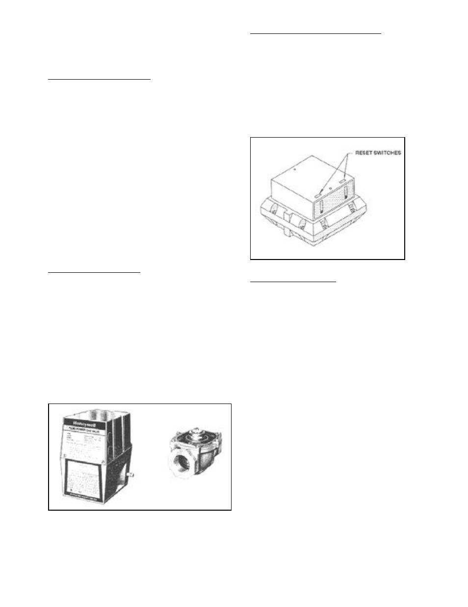
High-Low Gas Pressure Switch (FM/IRI)
(Aerovent Part #470-01E)
A high and low gas pressure switch is included with all
units. These switches monitor the gas pressure downstream
from the safety valves and shuts off the electric supply to
the safety valves if excessive or insufficient gas pressure is
experienced. This will shut down all gas flow to the burner.
The switches must be manually reset when the gas pressure
is returned to the set point pressure of the respective pres-
sure switches.
Normally Open Vent Valve
CAUTION:
Units mounted indoors and supplied with a vent valve
MUST have the vent valve vented to the outdoors. Venting
of the valve is the responsibility of the installer.
Normally, two motorized main gas valves are supplied
and an open vent valve is also supplied between the two
valves. The vent valve
MUST BE VENTED TO THE
OUTDOORS.
The ASCO vent valve is a normally open solenoid type
valve. This valve is normally open when the unit is not
operating. It vents the pipe connecting the two safety shut-
off valves to the outdoors.
The vent valve should be checked for proper operation
at least once a year at the beginning of the heating season.
Obviously, if this valve should fail, large quantities of fuel
would be wasted, as this would be bypassed to the outside.
The purpose of the vent valve is to divert the gas flow
to the outdoors in the event the first motorized valve fails
to close during a shut down operating condition.
Figure 13. Valve Actuator and Gas Valve
Figure 14. High/Low Gas Pressure Switch