Aerovent IM-500 User Manual
Page 12
12
Aerovent IM-500
outside air. When power is interrupted to the motors, the
return air damper closes and the profile damper opens. The
discharge damper closes also giving a 100% shut-off from
outside air.
CAUTION:
The building pressure control’s low pressure tap MUST
be vented to the outdoors and fitted with a wind and rain
shield.
The desired building pressure is maintained by adjusting
the pressure set point on the floating pressure switch. The
differential is adjusted by the null adjustment in the pres-
sure switch. The smaller the null zone the more sensitive
the setting. The larger the null zone, the less sensitive the
setting. Settings should be such that the dampers stabilize
and hunting of the damper motors does not occur. The
larger the null zone the more stable the control loop will be.
Reset Timer
(Aerovent Part #21749-01)
Timed bypass of the low temperature switch. A timed
freeze protection system is supplied with most units. This
system includes a reset timer and a discharge air tempera-
ture sensor (freeze stat). On initial start-up, the reset timer
allows the unit to go through the normal ignition sequence.
The reset timer is set to engage the discharge air sensor
after a period of 3 minutes. In the event the unit fails to fire
after this time period the discharge air sensor will sense the
cold air and will shut down the entire unit. This is done to
prevent freeze up of water lines and minimize discomfort
to personnel in the area.
Figure 15. Vent Valve
Building Pressure Controls (Optional)
When units are provided with an 80/20 recirculating fea-
ture, a separate outside air and return air damper control is
supplied with the unit.
The control includes a floating pressure switch. Units
utilizing a building pressure control are provided with an
outside air burner bypass damper and a return air damper.
The outside air burner bypass damper and return air damp-
er are controlled by a floating damper motors. The dampers
are connected to the motor by a damper linkage.
The purpose of the building pressure switch is to sense
the difference between the indoor building pressure and
outdoor atmospheric pressure. This system is used when
varying exhaust loads are handled by one make-up air unit.
As more exhaust fans are turned on, pressure in the
building will tend to become more negative. The building
pressure switch senses this change in pressure and causes
the floating damper motor to adjust its position to bring
the building pressure back to near atmospheric by intro-
ducing more outside air and reducing the amount of return
air supplied to the unit. The dampers can be adjusted for
a maximum of 100% outside air, and a minimum of 20%
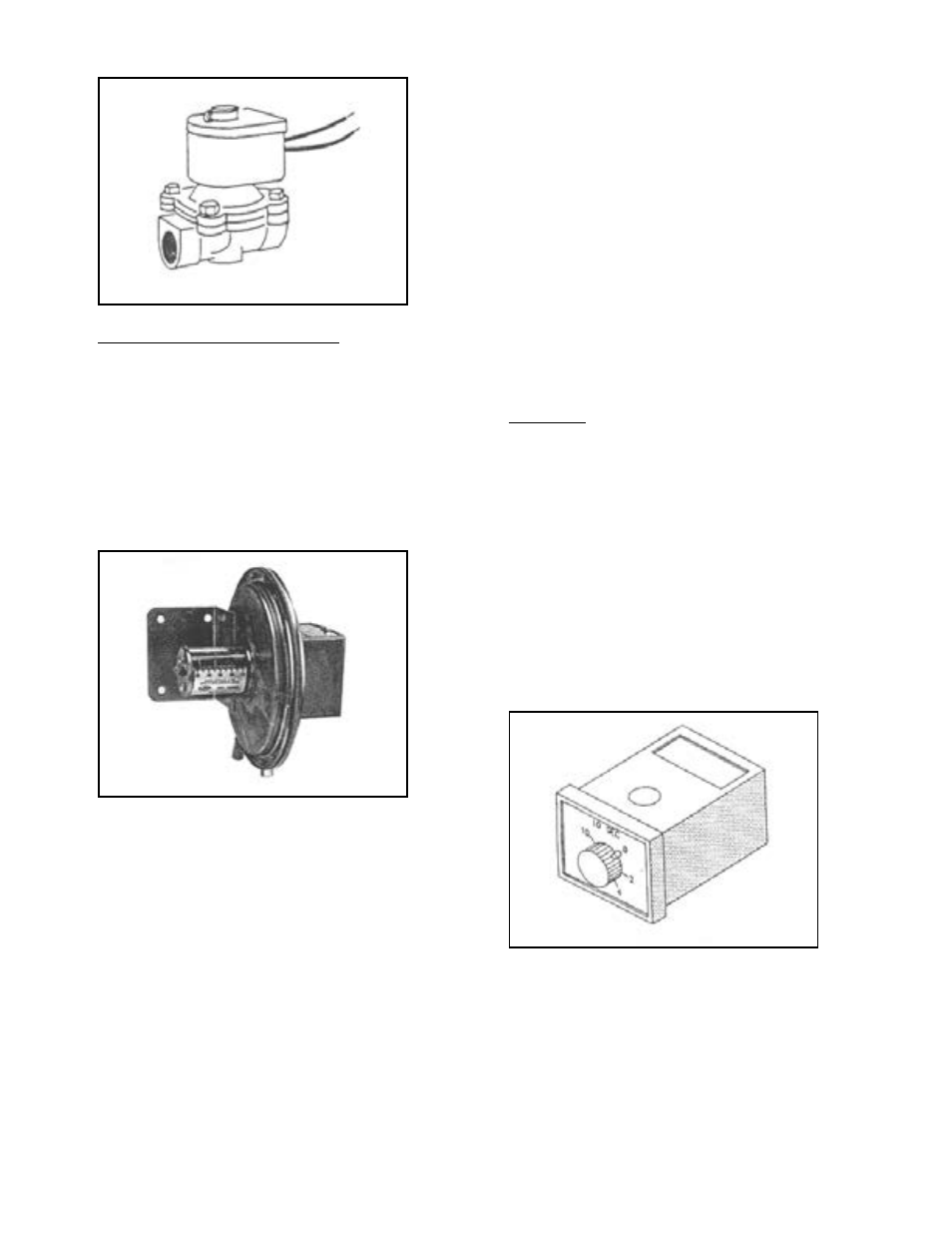
Figure 16. Floating Pressure Switch
Figure 17. Reset Timer