Snorkel Bi-Energy-sn4275+ User Manual
Page 12
Page 10
Operator Manual
067449-023 LX31/LX41 Electric and BiEnergy
Operation
L
E V E L I N G
T H E
P
L A T F O R M
( O
U T R I G G E R
E Q U I P P E D
M A C H I N E S
O N L Y
)
W A R N I N G
!
!
When using outriggers, all four (4) outriggers must be in firm contact with the supporting surface.
O
UTRIGGER
S
WITCHES AND
I
NDICATOR
L
IGHTS
For each outrigger, there is an outrigger switch and an outrigger indicator light (refer to Figure 2).
Each outrigger switch will raise and lower one outrigger.
Each outrigger indicator light will indicate the position of one outrigger.
• When the indicator light is OFF - the outrigger is fully retracted.
• When the indicator light is FLASHING - the outrigger is partially extended.
• When the indicator light is ON - the outrigger is in firm contact with the supporting surface.
T
O
L
E V E L
T H E
P
L A T F O R M
( E
X T E N D
T H E
O
U T R I G G E R S
)
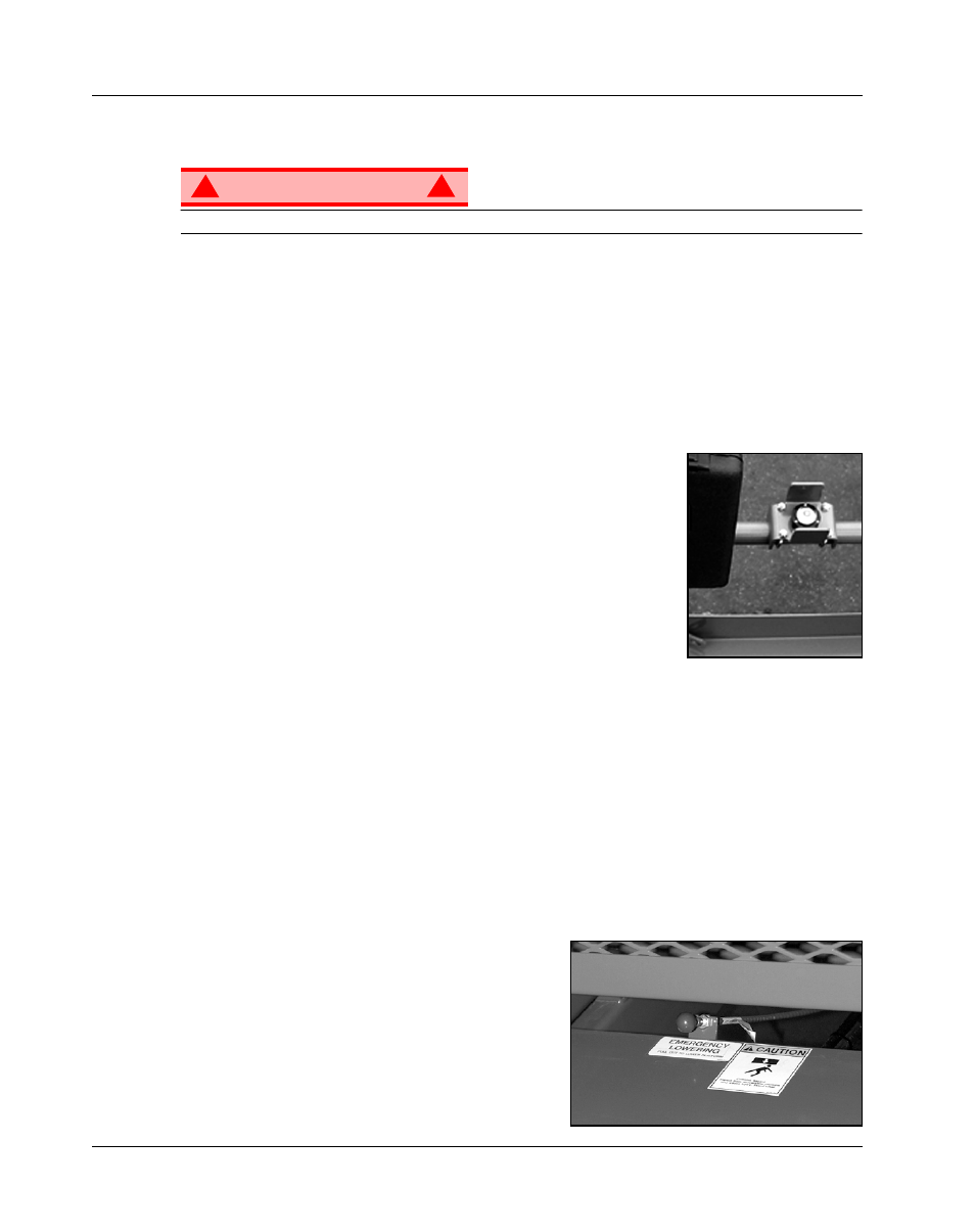
Figure 3: Platform Orbit Bubble Level
1. Make sure that the extension deck is retracted before operating the outrig-
gers.
2. Look around the machine; make sure that there is nothing obstructing the
outriggers, and that the surface beneath them is suitable to support the
weight of the machine.
3. Position the Lift/Outrigger/Drive switch set to OUTRIGGER.
4. Depress the interlock lever switch on the control lever, and operate the
outrigger switches to extend each outrigger until it is making firm contact
with the supporting surface.
5. While observing the bubble level on the guardrail, extend the outrigger
opposite the position of the bubble until the platform is level. For example:
if the bubble is to the front and left in the orbit, extend the rear right outrigger. Continue to adjust until
the bubble is centered in the small circle indicating that the platform is level.
6. Confirm that all four (4) outriggers are in firm contact with the supporting surface. The outriggers are in
contact with the supporting surface when the indicator lights are ON.
T
O
R
ETRACT THE
O
UTRIGGERS
1. Fully lower the platform.
2. Position the Lift/Outrigger/Drive switch set to OUTRIGGER.
3. Depress the interlock lever switch on the control lever, and position each outrigger switch to RETRACT.
• The outrigger indicator lights will be OFF when the outriggers are fully retracted.
• The drive enable indicator light will not come on until all four outriggers are fully retracted.
E
M E R G E N C Y
L
O W E R I N G
Figure 4: Emergency Lowering Valve,
The emergency lowering control knob is located at the
rear of the machine at the base of the scissor assembly.
1. Open the emergency lowering valve by pulling on the
knob and holding it.
2. Once the platform is fully lowered, release the knob to
close the valve.