Infinity supported application 33 – AEM Infinity Supported Applications - Ford Coyote Engine with Ford Racing Control Pack User Manual
Page 33
Infinity Supported Application
33
© 2014 AEM Performance Electronics
Infinity
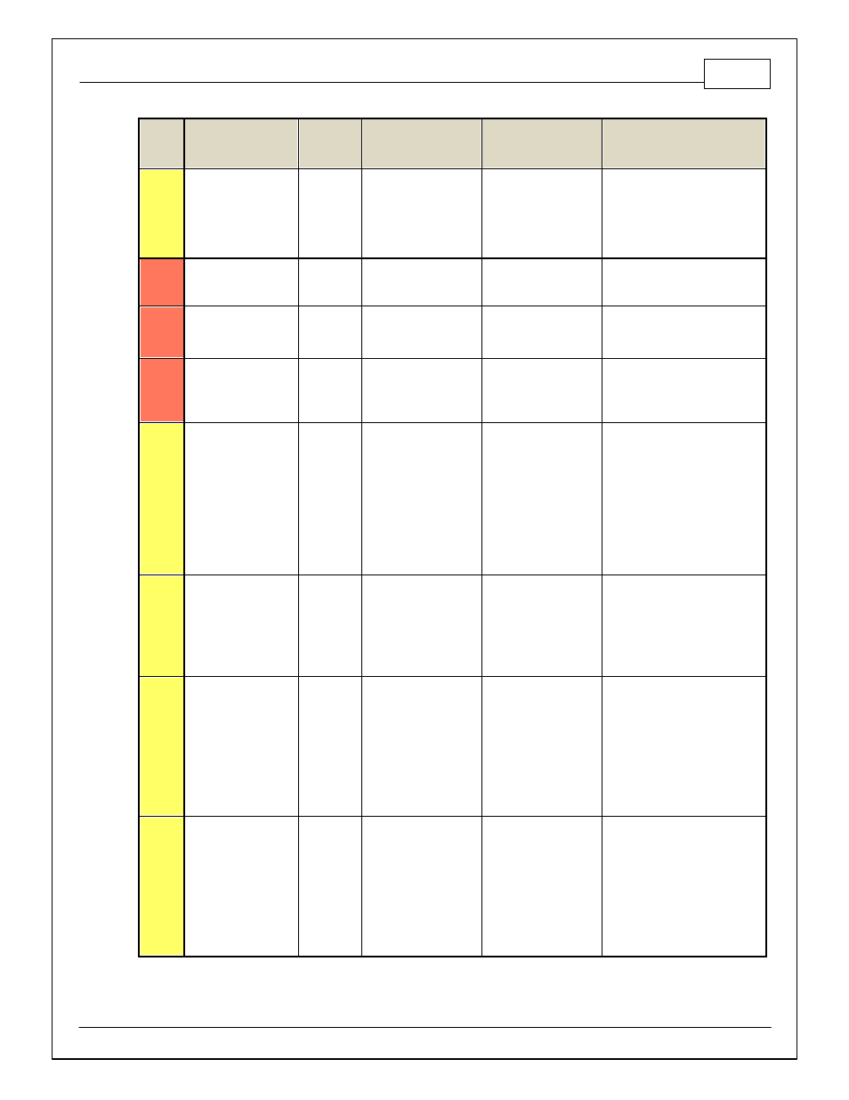
Pin
Infinity Assignment
Pin
Destination
Ford Coyote with FR
Control Pack
Description
Infinity Hardware
Specification
Notes
C2-29
LowsideSwitch_9
Ford Racing
PCM70-10
Tacho (CTO) Blunt Lead
Lowside switch, 4A max
with internal f ly back
diode, 2.2K 12V pullup.
Inductiv e load should
NOT hav e f ull time
power.
See Setup Wizard page 'Tacho' f or
conf iguration options.
C2-30
AGND_2
Engine
E-08
DBW Ground (ETCRTN)
Dedicated analog ground
Analog 0–5V sensor ground
C2-31
AGND_2
Engine E-06
&
Engine E-44
Knock Sensor 1 & 2
Ground [KS1 - & KS2 -]
Dedicated analog ground
Analog 0–5V sensor ground
C2-32
AGND_2
Ford Racing
PCM70-44
&
PCM70-60
APP Sensor 1 & 2
Ground
APPVREF (1) & (2)
Dedicated analog ground
Analog 0–5V sensor ground
C2-33
Analog_In_20
Ford Racing
PCM50-19
Clutch Position (Neutral
Switch) Blunt Lead
12 bit A/D, 100K pullup to
5V
0–5V analog signal. Use +5V Out
pins as power supply and Sensor
Ground pins as the low ref erence.
Do not connect signals ref erenced
to +12V as this can permanently
damage the ECU. See
ClutchSwitch 1-axis table f or setup
options. Input can be assigned to
dif f erent pins. See Setup Wizard
page 'Input Function Assignments'
f or input mapping options.
C2-34
Analog_In_21
---
3 Step Enable Switch /
TPS2A
12 bit A/D, 100K pullup to
5V
0–5V analog signal. Use +5V Out
pins as power supply and Sensor
Ground pins as the low ref erence.
Do not connect signals ref erenced
to +12V as this can permanently
damage the ECU. See 3StepSwitch
1-axis table f or setup.
C2-35
Analog_In_22
---
USB Logging Activ ate
12 bit A/D, 100K pullup to
5V
0–5V analog signal. Use +5V Out
pins as power supply and Sensor
Ground pins as the low ref erence.
Do not connect signals ref erenced
to +12V as this can permanently
damage the ECU. See
USBLoggingRequestIn channel f or
input state. See Setup Wizard page
'USB Logging' f or conf iguration
options.
C2-36
Analog_In_23
---
Charge Out Pressure /
TPS2B
12 bit A/D, 100K pullup to
5V
0–5V analog signal. Use +5V Out
pins as power supply and Sensor
Ground pins as the low ref erence.
Do not connect signals ref erenced
to +12V as this can permanently
damage the ECU. See
ChargeOutPress [kPa] channel f or
input state. See Setup Wizard page
'Charge Out Pressure' f or
calibration options.