AEM 30-3805 Universal V8 Core Harness User Manual
Page 33
33
© 2014 AEM Performance Electronics
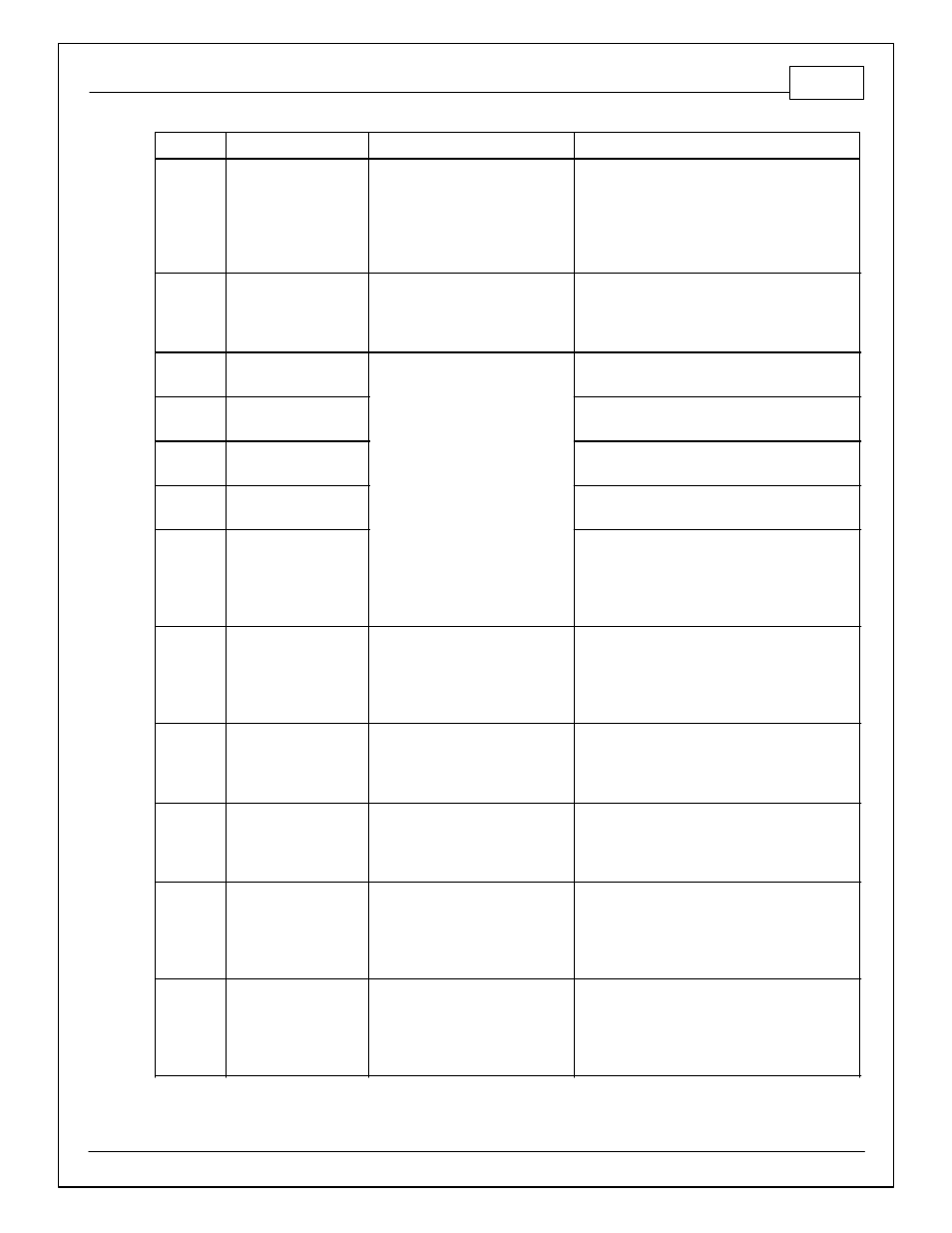
Infinity Pin
Hrdwr Ref.
Hardware Specification
Notes
C2-43
LowsideSwitch_8
Lowside switch, 4A max with
internal flyback diode. Inductive
load should NOT have full time
power.
Activates if any of the following flags are true:
OilPressProtectOut, LeanProtectOut,
CoolantProtect. Output can be assigned to other
functions. See Setup Wizard page LowSide
Assignment Tables for additional options.
C2-44
LowsideSwitch_7
Lowside switch, 4A max with
internal flyback diode. Inductive
load should NOT have full time
power.
Normally used as Spare GPO1 output.
C2-45
UEGO 2 VM
Bosch UEGO Controller
Virtual Ground signal. Connect to pin 5 of Bosch
UEGO sensor.
C2-46
UEGO 2 UN
Nernst Voltage signal. Connect to pin 1 of Bosch
UEGO sensor
C2-47
UEGO 2 IP
Pumping Current signal. Connect to pin 6 of Bosch
UEGO sensor
C2-48
UEGO 2 IA
Trim Current signal. Connect to pin 2 of Bosch
UEGO sensor
C2-49
UEGO 2 HEAT
Lowside switch for UEGO heater control. Connect
to pin 4 of Bosch UEGO sensor. NOTE that pin 3 of
the Sensor is heater (+) and must be power by a
fused/switched 12V supply.
C2-50
+12V_R8C_CPU
Dedicated power management CPU Optional full time battery power. MUST be
powered before the ignition switch input is
triggered (See C1-65).
C2-51
Coil 7
25 mA max source current
0-5V Falling edge fire. DO NOT connect directly to
coil primary. Must use an ignitor OR CDI that
accepts a FALLING edge fire signal.
C2-52
Coil 8
25 mA max source current
0-5V Falling edge fire. DO NOT connect directly to
coil primary. Must use an ignitor OR CDI that
accepts a FALLING edge fire signal.
C2-53
Coil 9
25 mA max source current
0-5V Falling edge fire. DO NOT connect directly to
coil primary. Must use an ignitor OR CDI that
accepts a FALLING edge fire signal.
C2-54
Coil 10
25 mA max source current
0-5V Falling edge fire. DO NOT connect directly to
coil primary. Must use an ignitor OR CDI that
accepts a FALLING edge fire signal.