3805 core harness pinouts, C1 infinity connector c1, Pin wire color gauge – AEM 30-3805 Universal V8 Core Harness User Manual
Page 10
AEM Infinity Harness Manuals
10
© 2014 AEM Performance Electronics
Auxiliary Connectors
The kit includes 2 optional connector kits that mate with connectors labeled Aux1 and
Aux2 on the main harness trunk. See the 3805 Core Harness Pinout section for details
on available functions. All default functions are listed in parentheses. Many are re-
assignable through the setup wizard interface.
8
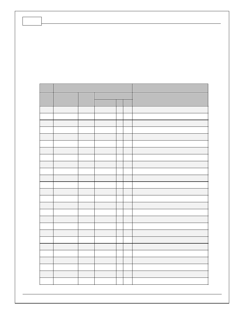
3805 Core Harness Pinouts
3805 - Infinity Pinout Universal V8
Default functions are listed in parentheses
C1
Infinity Connector C1
73 Way F Receptacle 0.64 2.8 Series Sealed (GY)
Pin
Wire Color Gauge
Destination
1
2
3
C1-1
---
C1-2
GRN
20
C8-1
LowsideSwitch_5
C1-3
ORG/RED
20
C11-5
LowsideSwitch_6
C1-4
WHT
18
C13-4
UEGO1_Heat
C1-5
GRN
20
C13-2
UEGO1_IA
C1-6
RED
20
C13-6
UEGO1_IP
C1-7
BLK
20
C13-1
UEGO1_UN
C1-8
ORN
20
C13-5
UEGO1_VM
C1-9
RED
20
C14-2
Flash_Enable
C1-10
RED
20
P1-8
+12V_R8C_CPU (Perm Power)
C1-11
DK GRN/WHT
20
C5-4
Coil4
C1-12
LT BLU
20
C5-3
Coil3
C1-13
RED/WHT
20
C5-2
Coil2
C1-14
VIO
20
C5-1
Coil1
C1-15
LT BLU/WHT
20
C5-10
Coil6
C1-16
DK GRN
20
C5-9
Coil5
C1-17
VIO
20
P1-37
LowsideSwitch_2 (Coolant Fan 1 Control)
C1-18
VIO/BLK
20
C8-3
LowsideSwitch_3 (MIL Output)
C1-19
BLK/WHT
20
S2
AGND_1 (Analog Sensor Ground)
C1-20
BLK/WHT
20
C10-2
AGND_1 (Analog Sensor Ground)
C1-21
WHT
20
C10-1
Crank Position Sensor (Hall Effect)
C1-22
GRN
20
C10-3
Camshaft Position Sensor 1 (Hall Effect)
C1-23
---
C1-24
---
C1-25
DK BLU/RED
20
C8-2
Digital_In_4 (Vehicle Speed Sensor Hall Effect)
C1-26
BLK/RED
20
C8-8
Digital_In_5 (Flex Fuel Sensor)