Pin wire color gauge, Injectors, Wheelspeeds – AEM 30-3805 Universal V8 Core Harness User Manual
Page 15: Aux2
15
© 2014 AEM Performance Electronics
11
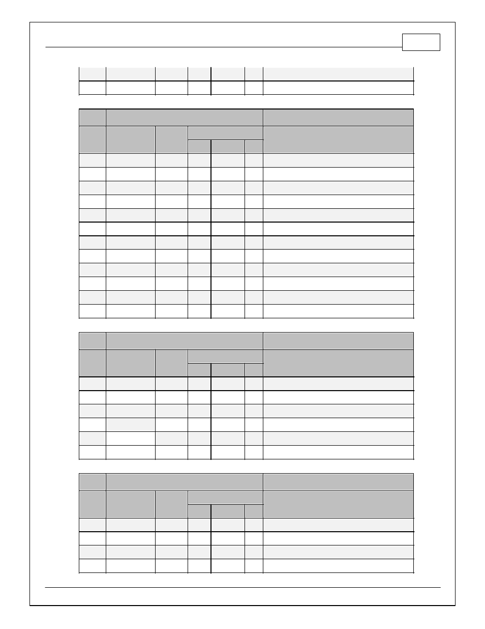
TAN
20
C2-51
Coil7
12
VIO/WHT
20
C2-52
Coil8
C6
DT Receptacle, 12 Way
Pin
Wire Color Gauge
Destination
Injectors
1
2
3
1
BLU
20
C1-63
Injector 1
2
LT GRN/BLK
20
C1-62
Injector 2
3
PNK/BLK
20
C1-59
Injector 3
4
LT BLU/BLK
20
C1-58
Injector 4
5
RED
18
C15-B
Fused +12V Relay Power
6
RED
18
C15-C
Fused +12V Relay Power
7
RED
18
C15-H
Fused +12V Relay Power
8
RED
18
C15-J
Fused +12V Relay Power
9
BLU/RED
20
C1-57
Injector 5
10
YEL/BLK
20
C1-56
Injector 6
11
RED/BLK
20
C2-4
Injector 7
12
DK BLU/WHT
20
C2-5
Injector 8
C7
DTM Receptacle, 6 Way
Pin
Wire Color Gauge
Destination
WheelSpeeds
1
2
3
1
WHT
20
C2-25
VR+_In_5 (Driven Rt Wheel VR+)
2
BLK
20
C2-26
VR-_In_5 (Driven Rt Wheel VR-)
3
4
WHT
20
C2-27
VR-_In_4 (Non Driven Rt Wheel VR-)
5
BLK
20
C2-28
VR+_In_4 (Non Driven Rt Wheel VR+)
6
BLK
22
S5
Shield Ground
C8
DTM Plug, 8 Way
Pin
Wire Color Gauge
Destination
Aux2
1
2
3
1
GRN
20
C1-2
LowsideSwitch_5
2
DK BLU/RED
20
C1-25
Digital_In_4 (Vehicle Speed Sensor Hall Effect)
3
VIO/BLK
20
C1-18
LowsideSwitch_3 (MIL Output)
4
WHT/RED
20
C1-33
LowsideSwitch_1 (Boost Control Solenoid)
- 30-71XX Infinity EMS Quick Start Guide (53 pages)
- 23-800BK Tru-Time Adjustable Cam Gear (7 pages)
- 23-801BK Tru-Time Adjustable Cam Gear (11 pages)
- 23-830BK Tru-Time Adjustable Cam Gear (8 pages)
- 23-831BK Tru-Time Adjustable Cam Gear (7 pages)
- 23-850BK Tru-Time Adjustable Cam Gear (6 pages)
- 23-851BK Tru-Time Adjustable Cam Gear (7 pages)
- 25-100BK High Volume Fuel Rail (5 pages)
- 25-104BK High Volume Fuel Rail (5 pages)
- 25-108BK High Volume Fuel Rail (7 pages)
- 25-109BK High Volume Fuel Rail (6 pages)
- 25-111BK High Volume Fuel Rail (6 pages)
- 25-130BK High Volume Fuel Rail (6 pages)
- 25-131BK High Volume Fuel Rail (4 pages)
- 25-200BK Honda/Acura High Volume Fuel Filter (3 pages)
- 25-201BK Universal High Volume Fuel Filter (4 pages)
- 25-300BK Honda/Acura Adjustable Fuel Pressure Regualtor (9 pages)
- 25-302BK Universal Adjustable Fuel Pressure Regualtor (5 pages)
- 25-391 High Volume Fuel Rail AN Adapter Kit (5 pages)
- 25-392 Honda/Acura Adjustable Fuel Pressure Regualtor (4 pages)
- 30-1910 Universal Fuel Ignition Controller 6 Channel (33 pages)
- 30-1930 Universal Fuel Ignition Controller 8 Channel (34 pages)
- 30-1960 Plug & Play Fuel Ignition Controller 6 Channel (5 pages)
- 30-2010 Air Temp Sensor Kit (2 pages)
- 30-2011 Water Temp Sensor Kit (2 pages)
- 30-2012 Water Temp Sensor Kit (2 pages)
- 30-2020 Bosch Injector Plug Kit 4 Pack (2 pages)
- 30-2050 RTD Temperature Sensor Kit (1 page)
- 30-2056 Universal 12 Position Trim Pot (1 page)
- 30-2065 K-Type Closed Tip Thermocouple Sensor Kit (2 pages)
- 30-2066 K-Type Closed Tip Thermocouple 10 Wiring Extension Kit (2 pages)
- 30-2067 X-WiFi K-Type Closed Tip Thermocouple Kit (2 pages)
- 30-2130-XXX Stainless Steel Pressure Sensor (2 pages)
- 30-2131-XXX Brass Pressure Sensor (2 pages)
- 30-2204 K-Type Thermocouple Amplifier 4 Channel (6 pages)
- 30-2310 Inline Wideband UEGO Controller (8 pages)
- 30-2067 X-WiFi Wideband UEGO & EGT Controller (14 pages)
- 30-2340 4-Channel Wideband UEGO AFR Controller (30 pages)
- 30-2340-N 4-Channel Wideband UEGO AFR Controller - For use with Nascar McLaren ECU (28 pages)
- 30-2355-XXX No-Weld O2 Sensor Mount (4 pages)
- 30-2400 Boost Control Solenoid Kit (2 pages)
- 30-2500 AQ-1 Data Logging System (22 pages)
- 30-2710 Peak & Hold Injector Driver 10 Channel (5 pages)
- 30-2840 4 Channel Coil Driver (2 pages)
- 30-2841 1 Channel Coil Driver (4 pages)