AEM 30-3805 Universal V8 Core Harness User Manual
Page 31
31
© 2014 AEM Performance Electronics
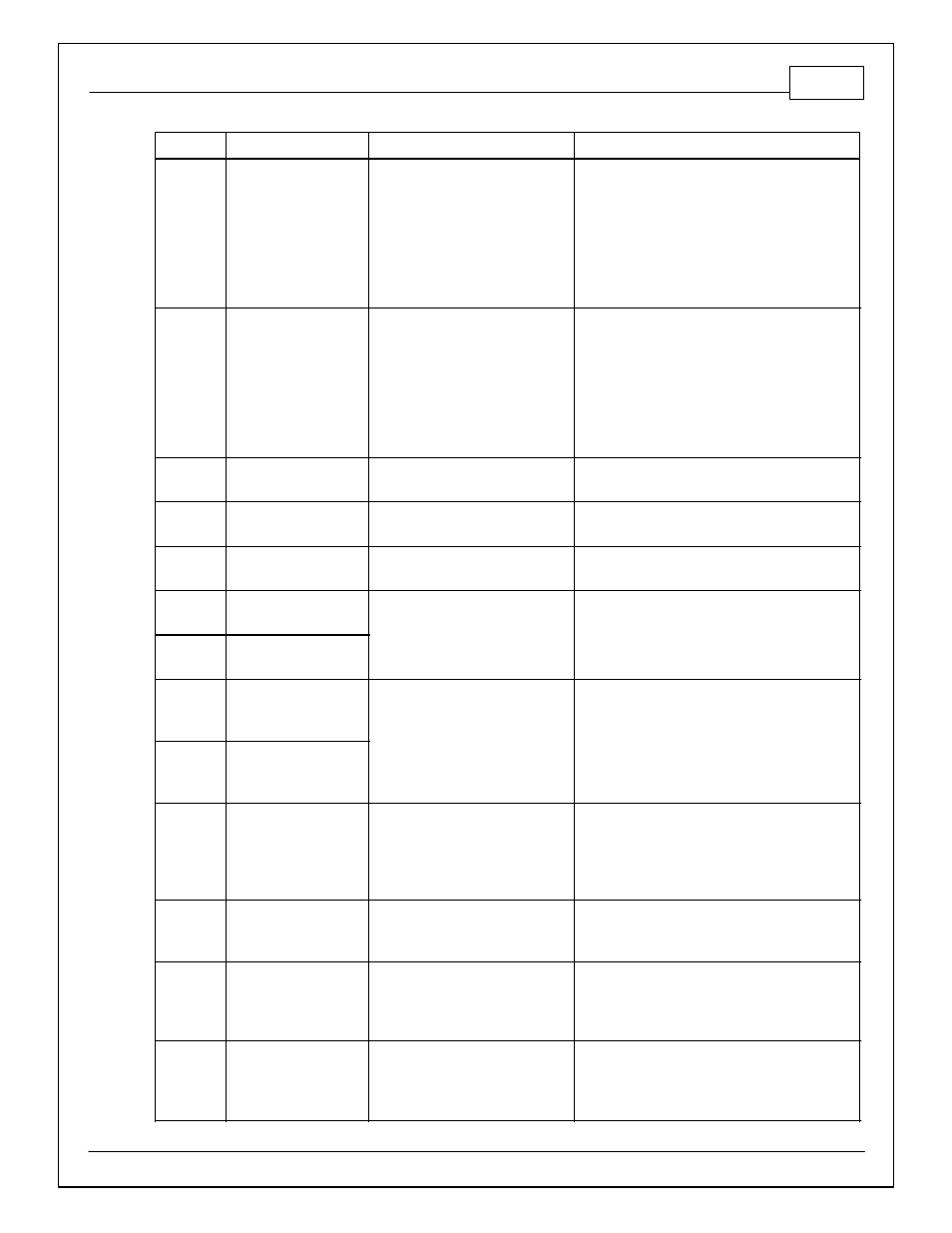
Infinity Pin
Hrdwr Ref.
Hardware Specification
Notes
C2-20
Analog_In_15
12 bit A/D, 100K pullup to 5V
0-5V analog signal. Use +5V Out pins as power
supply and Sensor Ground pins as the low
reference. Do not connect signals referenced to
+12V as this can permanently damage the ECU.
Normally used as Exhaust Back Pressure input.
C2-21
Analog_In_16
12 bit A/D, 100K pullup to 5V
0-5V analog signal. Use +5V Out pins as power
supply and Sensor Ground pins as the low
reference. Do not connect signals referenced to
+12V as this can permanently damage the ECU.
Normally used as DBW1_TPSB input.
C2-22
+5V_Out_2
Regulated, fused +5V supply for
sensor power
Analog sensor power
C2-23
+5V_Out_2
Regulated, fused +5V supply for
sensor power
Analog sensor power
C2-24
+5V_Out_2
Regulated, fused +5V supply for
sensor power
Analog sensor power
C2-25
VR+_In_5
Differential Variable Reluctance
Zero Cross Detection
See Driven Wheel Speed Calibration in the Setup
Wizard Vehicle Speed page.
C2-26
VR-_In_5
C2-27
VR-_In_4
Differential Variable Reluctance
Zero Cross Detection
See Non Driven Wheel Speed Calibration in the
Setup Wizard Vehicle Speed page.
C2-28
V R+_In_4
C2-29
LowsideSwitch_9
Lowside switch, 4A max with
internal flyback diode, 2.2K 12V
pullup. Inductive load should NOT
have full time power.
See Setup Wizard page Tacho for configuration
options.
C2-30
AGND_2
Dedicated analog ground
Analog 0-5V sensor ground
C2-31
AGND_2
Dedicated analog ground
Analog 0-5V sensor ground
C2-32
AGND_2
Dedicated analog ground
Analog 0-5V sensor ground