OR-Fab 89000 ORF PRODUCT DISPLAY RACK User Manual
Page 3
3
DISPLAY RACK #89000
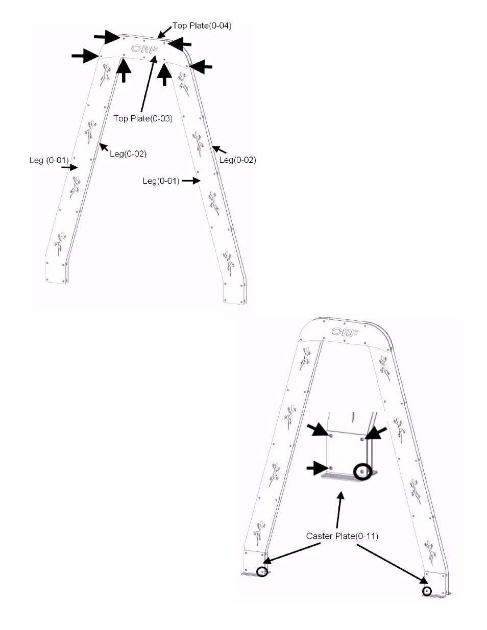
Step 1:
Locate 1 kit top plate (0-03) and 2 kit leg
(0-01).
Use 6 kit 3/8”x 2 1/4” bolts & washers through
both kit top plate (0-03) and 2 kit legs (0-01)
to assemble front side of display “A”-frame.
(Reference arrows for placement.)
Step 2:
Install 6 kit 1” spacers tubes onto inside of kit
3/8” bolts and kit plates.
Locate 1 kit top plate (0-04) and 2 kit legs
(0-02).
Install 2 kit legs (0-02) on top of kit 1” spacer
tubes and through 3/8” bolts; then 1 kit top
plate (0-04) on top of 2 kit legs (0-02).
Use 6 kit 3/8” flange nuts to secure the
upper “A”-frame assembly. (Note: Do not
tighten kit hardware at this time.)
Step 3:
Locate 2 kit caster plate (0-11) for each
“A”-frame leg.
Use 3 kit 3/8”x 2 1/4” bolts, washers and 3 kit
1” spacer tubes through both kit legs (0-01)
& (0-02) to assemble bottom side of display
“A”-frame.
(Reference arrows for placement.)
Repeat process to each leg.
(Note: Do not install bolt or spacer in circled
area at this time. Kit 3/8” nut may be use to
hold assembly together temporarily.)
- 86300 PRE RUNNER TIRE CARRIER - ALL PICKUPS (3 pages)
- 87030 DEF Skid Plate For 2011 - 2015 Chevy/GMC 2500 HD Duramax Diesel Pickups (2 pages)
- 89601 PRO LIGHT BAR - CHEVY 2500/3500 (3 pages)
- 87041 00-06 TOYOTA TUNDRA / 01-07 SEQUOIA TRANS. SKID PLATE/CAT THEFT SHIELD (2 pages)
- 89500 PRO-LIGHT BAR - FORD F150 4-DOOR (2 pages)
- 87042 TUNDRA/08-13 SEQUOIA TRANSMISSION SKID PLATE CAT THEFT (2 pages)
- 83095 JEEP YJ ROCK SLIDER FRONT BUMPER (2 pages)
- 83100 ROCK SLIDER REAR BUMPER CJ / TJ / TJL (2 pages)
- 83202 JEEP CHEROKEE - XJ NON-WINCH FRONT BUMPER (12 pages)
- 83204 OEM Light Mount Rock Slider Front Bumper for Jeep JKs (5 pages)
- 83205 ROCK SLIDER REAR BUMPER JEEP JK - 2/4 DOOR (6 pages)
- 83208 3/16 PLATE METAL REAR BUMPER FOR JEEP JK - 2/4 DOOR (4 pages)
- 83209 JEEP XJ CHEROKEE REAR TUBE BUMPER (5 pages)
- 83210 OR-Fabs Front Stinger Bumper for Jeep JKs - Centered Winch Mount (7 pages)
- 83218 JK REAR PLATE METAL BUMPER W/ LED BACKUP LIGHTS (5 pages)
- 83233 JK WRANGLER HD MID WIDTH OFFSET WINCH FRONT BUMPER (5 pages)
- 83235 JK WRANGLER HD FULL WIDTH FRONT BUMPER (4 pages)
- 83240 JEEP CHEROKEE XJ FRONT HD BUMPER WITH HOOP (10 pages)
- 83245 JEEP CHEROKEE XJ HD COMP CUT REAR BUMPER (CUT & FOLDED) REAR LOWER QUARTERS (8 pages)
- 83250 XJ CHEROKEE HD REAR BUMPER (4 pages)
- 83640 REAR ROCKSLIDER SHEET METAL BUMPER / TJ / TJL (2 pages)
- 83660 JEEP TJ FRONT WINCH BUMPER (2 pages)
- 83665 TJ WRANGLER HD FULL WIDTH FRONT WINCH BUMPER W/ HOOP (2 pages)
- 84095 ROCK SLIDER SIDE BAR YJ (1 page)
- 84200 ROCKER PANEL S1 (PAIR) TJ (9 pages)
- 84207 ROCKER PANEL W/ BAR - JK WRANGLER 2-DOOR (5 pages)
- 84310 ROCKER SIDE ARMOR WRANGLER JK 2-DOOR (3 pages)
- 84330 JK 2 DOOR QUARTER ARMOR W/ MAXXIMA LAMPS (10 pages)
- 84400 JEEP CHEROKEE XJ QUARTER ARMOR (3 pages)
- 84460 XJ CHEROKEE HD ROCK SLIDERS (4 pages)
- 85095 JEEP YJ SWING AWAY SPARE TIRE/CAN CARRIER (12 pages)
- 85207 JEEP JK WRANGLER SWING AWAY SPARE TIRE/GERRY CAN CARRIER (9 pages)
- 85209 JEEP WRANGLER JK SWING AWAY SPARE TIRE CARRIER WITH ROTOPAX CONTAINERS (9 pages)
- 87007 JK ROCK SLIDER FRONT SWAY BAR DISCONNECT SKID PLATE (3 pages)
- 87011 MULTI LIGHT MOUNT KIT ALL ORF BUMPERS (1 page)
- 87013 JEEP FUEL CAN ADAPTER KIT FOR NON-LIP GAS CAN (2 pages)
- 87016 BUMPER GRILL GUARD HOOP (2 pages)
- 87017 JEEP THIRD BRAKE LIGHT MOUNT FOR OR-FAB SPARE TIRE CARRIERS (4 pages)
- 87022 Winch Mounting Plate -- Fits OR-Fab Rock Slider Non-Winch Front Bumpers for Jeep JKs (1 page)
- 87024 JK WINDSHIELD LIGHT MOUNT SYSTEM (3 pages)
- 87025 ROCK DOOR MIRROR RELOCATION BRACKETS (2 pages)
- 87031 ROTOPAX FUEL CAN CARRIER ADAPTER BRACKET KIT (2 pages)
- 87034 JK WRANGLER HD TRANSMISSION CROSS MEMBER (4 pages)
- 87035 TIRE CARRIER T-HANDLE LICENSE PLATE RELOCATION BRACKET (2 pages)
- 87046 2012-2015 Jeep JK Vacuum Pump Relocation Kit (3 pages)