2 inputs via rcvds05, 3 5-cable input, 20 3.5.3 5-cable input – Barco R9001960 User Manual
Page 24: Connections set up of the input selection, 2 inputs via rcvds05 overview, 3 5-cable input where to find
3. Connections
Set up of the input selection
1. Press ENTER to start up the adjustment mode.
2. Press the cursor keys to select Installation. (menu 3-1)
3. Press ENTER to display the Installation menu.
4. Press the cursor keys to select Input slots. (menu 3-2)
5. Press ENTER to display the Input Slots menu.
6. Press the cursor keys to select Slot Selector. (menu 3-3)
7. Press ENTER to toggle between [Manual] or [Automatic].
8. Press EXIT several times to leave the adjustment mode.
ADJUSTMENT MODE
Select a path from below :
AUTO IMAGE
RANDOM ACCESS
INSTALLATION
SERVICE
Source 01
Select with
↑
or
↓
then
Menu 3-1
INSTALLATION
INPUT SLOTS
NO SIGNAL
LENS
TEXT BOX POSITION
QUICK ACCESS KEYS
START UP MODE
NETWORK CONFIGURATION
more ...
Select with
↑
or
↓
then
Menu 3-2
INPUT SLOTS
SLOT SELECTOR [Automatic]
x 1. RGB [HV&VS]
- 2. RGB [HV&VS]
- 3. VIDEO
- 4. S-VIDEO
- 5. DIGITAL INPUT
- 6. IEEE 1394
Select with
↑
or
↓
Menu 3-3
3.5.2 Inputs via RCVDS05
Overview
When using a RCVDS05, it is recommended to use a 5-cable output module in the RCVDS. The outputs of this module have to be
connected to the 5 cable input (slot 1) of the projector. To switch the projector in the 5-cable mode see chapter ’Installation mode’.
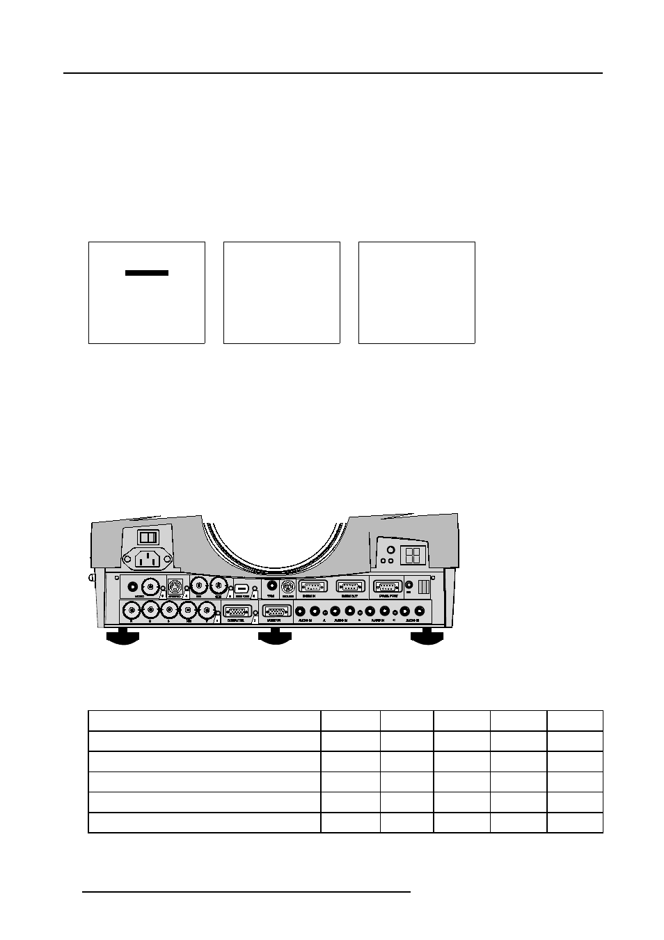
3.5.3 5-cable input
Where to find ?
Slot 1 has 5 BNC input terminals. These are in the left corner on the front panel.
Image 3-5
Overview possible connections
Which signals can be connected to the 5 cable input.
The following signals can be connected to these BNC connectors :
Connector name
R
G
B
H
V
RGBHV
R
G
B
H
V
RGBS
R
G
B
S
-
RGsB
R
Gs
B
-
-
Composite video
-
Video
-
-
-
Super Video
-
Y
-
-
C
20
R5976182 BARCOREALITY 6500 30012001