1 afe calibrations, 1 dc offset calibration, 2 gain calibration – Cirrus Logic AN366 User Manual
Page 8: An366, Value: 0.6 - the current rms register, i, Value: 0.6 - the active power register, p, Value: 0.6
AN366
8
AN366REV2
4.1 AFE Calibrations
The CS5480/84/90 AFE incorporates three calibrations: gain, AC offset, and DC offset. Gain calibration is al-
ways required. AC offset calibration is only required when I
RMS
needs to be accurate at low input levels. DC
offset calibration is made available but not recommended for AC power meters. Instead, high-pass filters are
used to remove DC offset. The high-pass filter included in the CS5480/84/90 will remove any DC offset in real
time, and it is the best choice for AC power meters.
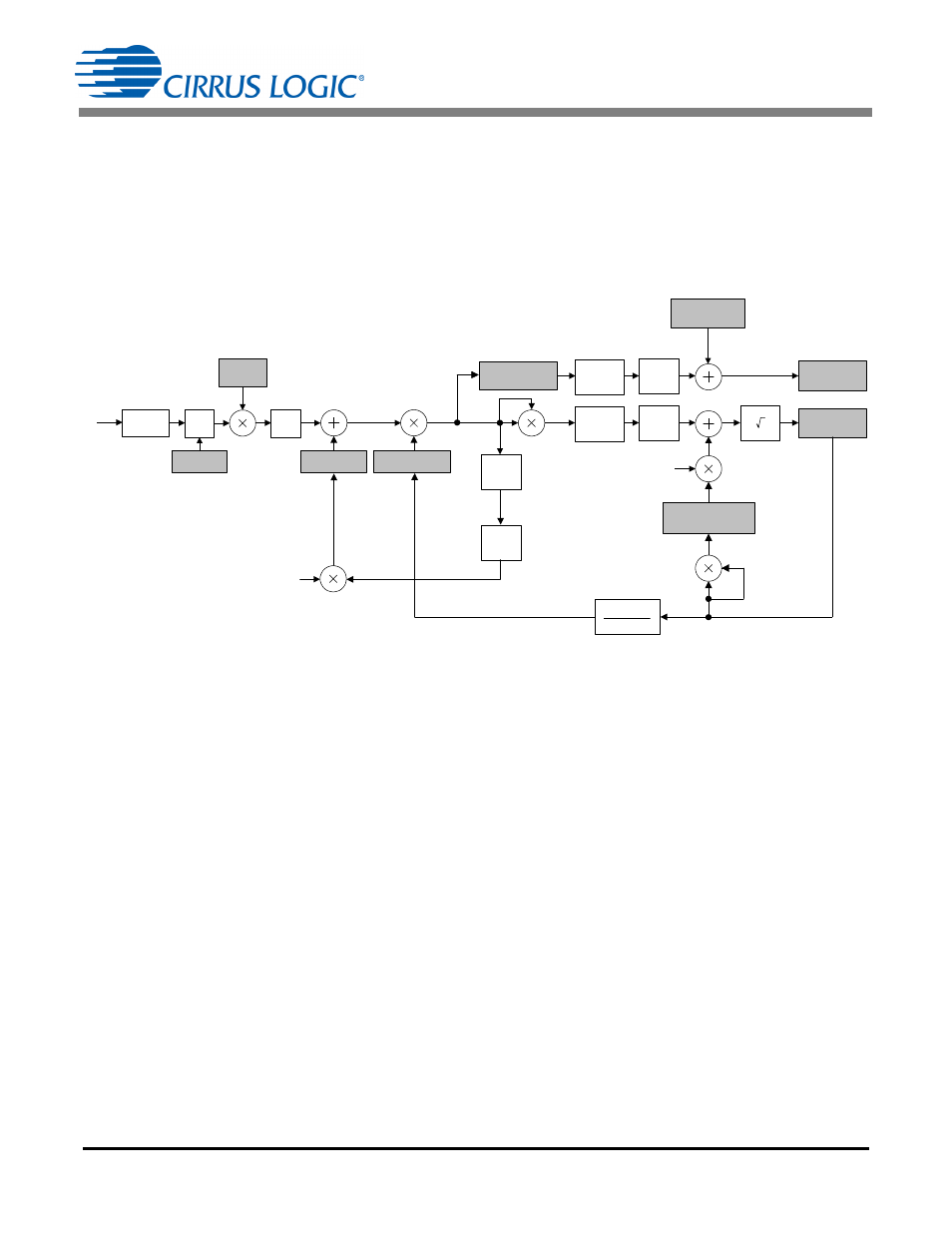
Figure 5 shows a flow diagram of the calibration process included in the Cirrus AFE. Refer to the CS5480/84/90
data sheet for detailed information.
Figure 5. Calibration Data Flow
4.1.1 DC Offset Calibration
DC offset calibration is designed to remove the DC component from the ADC output. DC offset calibration
is seldom used in AC power meters. The high-pass filter is the recommended choice and should be enabled
at the modulator output, as illustrated in Figure 5.
4.1.2 Gain Calibration
Gain calibration will adjust the input for hardware and sensor variations and customer-specific inputs. It is
recommended to use full-load conditions (full-scale voltage and current). (For non-full-load conditions, see
section 4.1.2.1 on page 8). When the full current load is not available, the CS5480/84/90 allows the scale
register to adjust for lower current loads to be provided. (See 3.3 on page 4 for adjusting the scale register.)
After gain calibration, full-scale input will yield:
-
The Voltage RMS register, V
RMS
, value: 0.6
-
The Current RMS register, I
RMS
, value: 0.6
-
The Active Power register, P
AVG
, value: 0.6
0.6 = 0.36 at PF = 1
-
The Reactive Power register, Q
AVG
, value: 0.6
0.6 = 0.36 at PF = 0
-
The Apparent Power register, S, value: 0.6
0.6 = 0.36
4.1.2.1
When AC Source or AC Load Are Less Than Ideal
If the AC source or AC load are less than ideal, the meter can still be calibrated with an accurate reference
meter using the Non-full-scale Gain Calibration procedure on page 9. It is common to see an AC load set to
15A actually measure in the range of 14.55A to 15.45A using a reference meter. When using the full-scale
current, it may be necessary to use the Non-full-scale Gain Calibration procedure on page 9 to account for
inaccurate resources.
V
RMS
*
, I
RMS
*
Registers
V
*
, I
*
, P
*
, Q
*
Registers
N
I
GAIN
*
, V
GAIN
*
Registers
*
Denotes readable/writable register
Ϯ Applies only to the current path
N
N
-1
N
DC
RMS
-1
RMS
0.6(Scale
*
Ϯ
)
P
AVG
*
, Q
AVG
*
Registers
N
N
Modulator
I
DCOFF
*
, V
DCOFF
*
Registers
PC
Register
Sinc
IIR
SYS
GAIN
Register
IN
P
OFF
*
, Q
OFF
*
Registers
I
ACOFF
*
Ϯ
Register