An366, Figure 10. ac offset calibration flow, Figure 11. dc offset calibration flow – Cirrus Logic AN366 User Manual
Page 17: Figure 12. no load offsets calibration flow
AN366
AN366REV2
17
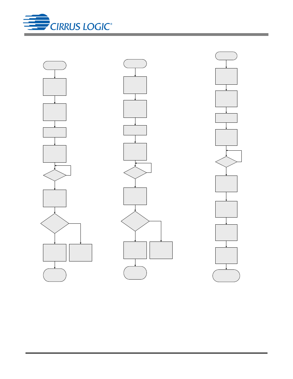
FROM MAIN
FLOW
CLEAR DRDY
SEND AC
OFFSET
CALIBRATION
0xF6
REMOVE LOAD
CURRENT
READ IRMS,
IACOFF
DRDY
SET?
CHECK
INPUT
OR
FAIL
RETURN
IACOFF
to
MAIN FLOW
IACOFF = 0
?
AC OFFSET
CALIBRATION
COMPLETE
Tsettle = 2000
SampleCount
N = 16000
NO
YES
YES
NO
Figure 10. AC Offset
Calibration Flow
Note: For an expanded view showing
more information about the AC offset
calibration flow, see AC Offset Calibration
Flow Diagram on page 44.
FROM MAIN
FLOW
CLEAR DRDY
SEND DC
OFFSET
CALIBRATION
0xE6
SHORT
VOLTAGE AND
CURRENT
INPUTS
READ IRMS,
VRMS, IDCOFF,
VDCOFF
DRDY
SET ?
CHECK
INPUT
OR
FAIL
RETURN
IDCOFF
VDCOFF
to
MAIN FLOW
IDCOFF = 0 ?
or
VDCOFF = 0 ?
DC OFFSET
CALIBRATION
COMPLETE
Tsettle = 2000
SampleCount
N = 16000
NO
YES
YES
NO
Figure 11. DC Offset
Calibration Flow
Note: For an expanded view showing
more information about the DC offset
calibration flow, see DC Offset
Calibration Flow Diagram on page 46.
FROM MAIN
FLOW
APPLY FULL
SCALE VOLTAGE
AND ZERO LOAD
CURRENT
READ PAVG and
QAVG
DRDY
SET ?
RETURN
POFF
QOFF
to
MAIN FLOW
POWER OFFSET
CALIBRATION
COMPLETE
Tsettle = 2000
SampleCount
N = 16000
NEGATE
QAVG
& STORE IN
QOFF
NEGATE
PAVG
& STORE IN
POFF
START
CONTINUOUS
CONVERT
0xD5
NO
YES
CLEAR DRDY
Figure 12. No Load Offsets
Calibration Flow
Note: For more information, see No Load
Offset Compensation Flow Diagram on
page 47.