3 dc offset calibration flow diagram, An366, Figure 42. conversion window – Cirrus Logic AN366 User Manual
Page 46
AN366
46
6.2.3 DC Offset Calibration Flow Diagram
The implemented of DC offset calibration follows the same structure as AC offset except that the voltage
and current source are both zero. The high pass filters must not be enabled and instead of sending AC Cal-
ibration command (F6), the DC Calibration command is sent (E6). Refer to the main flow for reading the DC
offset registers.
READ POWER REGISTERS
Reading IRMS is shown in main flow (see Figure 42).
SDI = 0x90
0x25 0xFFFFFF
Read I1ACOFF (page 16, register 37)
SDO = 0xFF
0xFF 0x050704
(0.0392766)
SDI = 0x90
0x2C 0xFFFFFF
Read I2ACOFF (page 16, register 44)
SDO = 0xFF
0xFF 0x049959
(0.0359298)
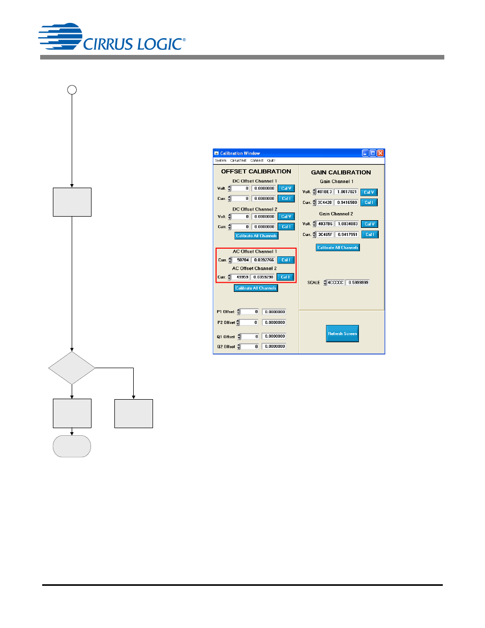
Figure 42. Conversion Window
PC/Controller tests for change in IACOFF register to check for success.
CHECK
INPUT
OR
FAIL
RETURN
IACOFF
to
MAIN FLOW
IACOFF = 0?
AC OFFSET
CALIBRATION
COMPLETE
NO
YES
READ IRMS,
IACOFF
2
- CobraNet (147 pages)
- CS4961xx (54 pages)
- CS150x (8 pages)
- CS1501 (16 pages)
- CS1601 (2 pages)
- CS1601 (16 pages)
- CS1610 (16 pages)
- CRD1610-8W (24 pages)
- CRD1611-8W (25 pages)
- CDB1610-8W (21 pages)
- CS1610A (18 pages)
- CDB1611-8W (21 pages)
- CDB1610A-8W (21 pages)
- CDB1611A-8W (21 pages)
- CRD1610A-8W (24 pages)
- CRD1611A-8W (25 pages)
- CS1615 (16 pages)
- AN403 (15 pages)
- AN401 (14 pages)
- AN400 (15 pages)
- AN375 (27 pages)
- AN376 (9 pages)
- CRD1615-8W (22 pages)
- CRD1616-8W (23 pages)
- AN402 (14 pages)
- AN404 (15 pages)
- CRD1615A-8W (21 pages)
- CS1615A (16 pages)
- CS1630 (56 pages)
- AN374 (35 pages)
- AN368 (80 pages)
- CRD1630-10W (24 pages)
- CRD1631-10W (25 pages)
- CS1680 (16 pages)
- AN405 (13 pages)
- AN379 (31 pages)
- CRD1680-7W (31 pages)
- AN335 (10 pages)
- AN334 (6 pages)
- AN312 (14 pages)
- AN Integrating CobraNet into Audio Products (16 pages)
- CobraNet Audio Routing Primer (9 pages)
- Bundle Assignments in CobraNet Systems (3 pages)
- CS2300-01 (3 pages)
- CS2000-CP (38 pages)