An366, Figure 8. main calibration flow – Cirrus Logic AN366 User Manual
Page 15
AN366
AN366REV2
15
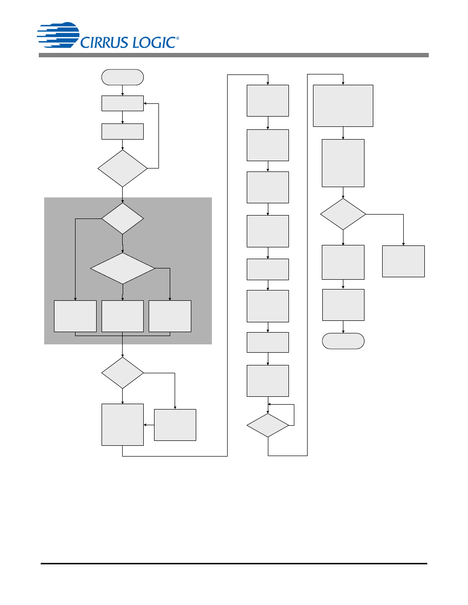
RESET
(See Note 1)
ROGOWSKI
SENSOR?
ENABLE
HIGH PASS
FILTER
ENABLE
INTEGRATOR on
CURRENT &
HIGH PASS on
VOLTAGE
FULL LOAD
AVAILABLE?
APPLY
REFERENCE
LINE VOLTAGE
AND LOAD
CURRENT
(Note 5)
SET SCALE
REGISTER
0.6 · LOAD ÷ FS
(Note 6)
READ
IRMS, VRMS,
PAVG, QAVG, PF
START
CONTINUOUS
CONVERT
0xD5
STOP
CONVERSIONS
0xD8
SEND AC GAIN
CALIBRATION
0xFE
ACCURACY
IN SPEC?
CHECK
SETUP or
FAIL
READ VGAIN,
IGAIN, IACOFF,
POFF, QOFF, PC,
RegChk
STORE
CALIBRATION
CONSTANTS &
REGISTER
CHECKSUM
POWER UP
CALIBRATION
COMPLETE
DC
MEASUREMENT?
PERFORM
DC
CALIBRATION
DRDY
SET?
SINGLE
CONVERSION
YES
NO
YES
NO
YES
NO
YES
NO
YES
NO
YES
NO
VALID RESET
CHECKSUM?
(Note 3)
CONFIRM
REFERENCE
SIGNALS ARE
APPLIED
CORRECTLY
Tsettle =
2000ms
(Note 2)
SampleCount (N)=
16,000
(Note 2)
START
CONTINUOUS
CONVERSION
AND VERIFY
METER
ACCURACY
CLEAR
DRDY
PERFORM PHASE
COMPENSATION,
IACOFF CALIBRATION,
and POWER OFFSET
CORRECTION if
NECESSARY
Note 1: The default setting for all registers should be set before performing calibration. Resetting the device restores the default setting
for all registers.
Note 2: Larger numbers in the Tsettle and SampleCount registers will increase calibration precision.
Note 3: Other configurations and controls might be necessary.
Note 4: For an expanded view showing more information about the main calibration flow, see Main Calibration Flow Diagram Using the
CDB5484 on page 29.
Note 5: See Non-full-scale Gain Calibration on page 9.
Note 6: Scale register is only in calibration path and does not require resetting to 0.6 after the calibration.
Figure 8. Main Calibration Flow